Modular lift assembly

a technology of modular lifts and components, applied in the direction of hoisting equipment, stage arrangements, theatre/circus, etc., can solve the problems of reducing the effective weight of the battens and any associated load, typical counterweight systems represent a significant cost, and the simple installation of counterweight systems is costly and cumbersome. achieve the effect of convenient configuration and convenient installation

Inactive Publication Date: 2009-02-19
ELECTRONIC THEATRE CONTROLS
View PDF82 Cites 4 Cited by
  • Summary
  • Abstract
  • Description
  • Claims
  • Application Information

AI Technical Summary

Benefits of technology

[0012]The present inventor has recognized, among other things, that a need exists for a lift assembly that can replace traditional counterweight systems. The need further exists for a lift assembly that can be readily installed into a variety of building configurations and layouts. A need further exists for a lift assembly having a modular construction to facilitate configuration to any of a variety of installations. A need also exists for a lift assembly that can maintain a predetermined fleet angle during raising or lowering of a load.
[0014]In a further configuration, the present lift assembly can include a bias mechanism such as a torsion spring connected between the frame and the drum for reducing the effective weight of the load or batten and any associated equipment.
[0016]The lift assembly further contemplates a load brake for reducing the risks associated with drive or motor failures. In addition, the present lift assembly contemplates a clip assembly for readily engaging the frame with structural beams, which can have any of a variety of dimensions. In addition, a power / control strip can be provided for supplying the power to a lift assembly as well as control signals.
[0018]The present lift assembly provides a turnkey lift assembly having rigging; power and control for the manipulation of battens, without requiring construction of traditional counterweight systems or relying on previously installed counterweight systems.

Problems solved by technology

The counterweights reduce the effective weight of the battens and any associated loads.
A typical counterweight system represents a significant cost.
Therefore, a substantial cost is incurred in the mere installation of a counterweight system.
Occasionally in expensive operations, a hydraulic or pneumatic motorized winch or cylinder device is used to raise and lower the batten.
In this rigging design, however, a number of additional bags can be added to the set of rope lines, and thereby exceed the safe limit of suspension ropes and defeat the overload-limiting feature.
Hand operated winches will occasionally free run when heavily loaded and will then dangerously drop the suspended load.
Other types of hand winches use a ratchet lock, but again these winches are also susceptible to free running when they are heavily loaded and hand operated.

Method used


Image

  • Modular lift assembly
  • Modular lift assembly
  • Modular lift assembly

Examples


Embodiment Construction

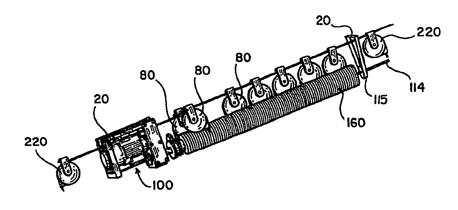
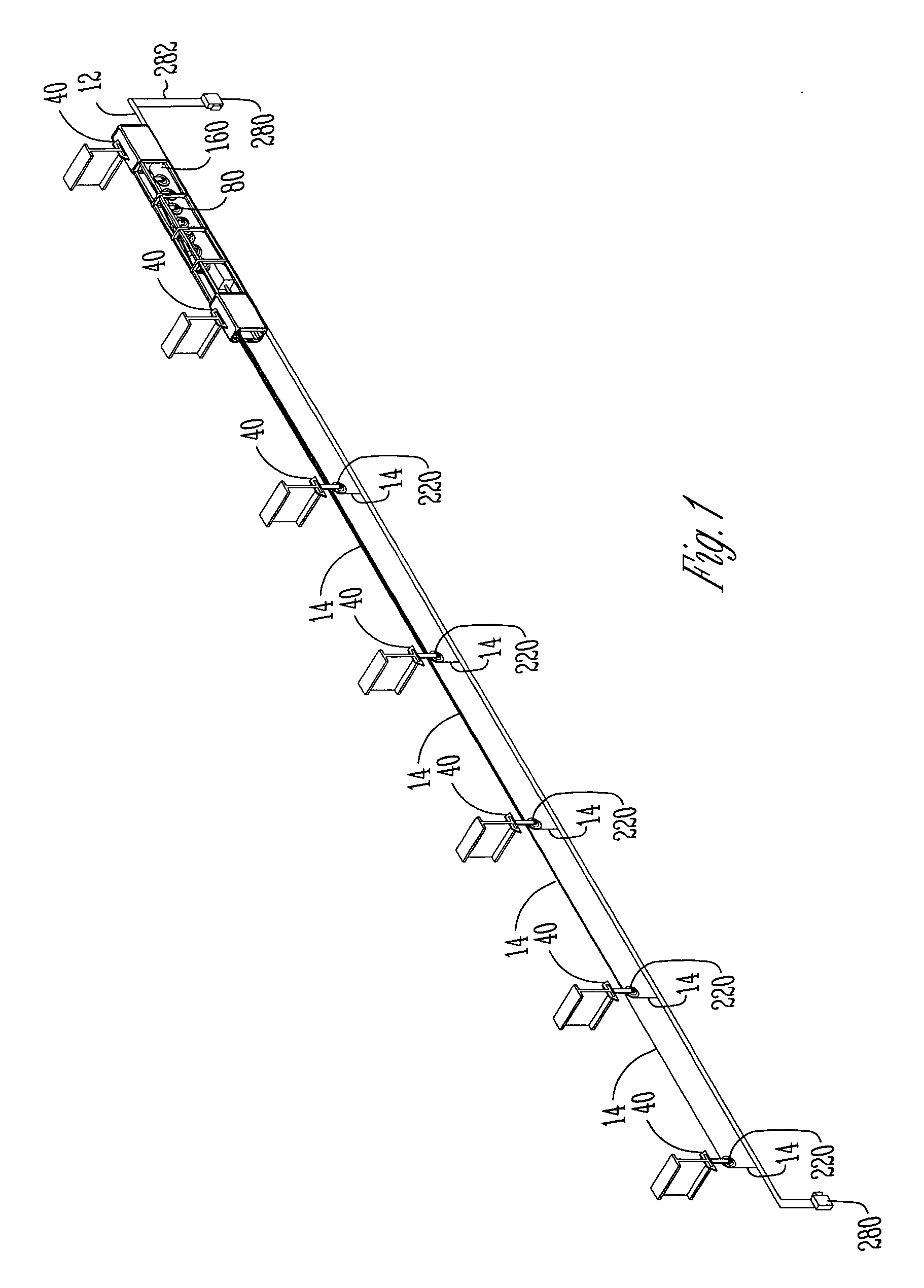
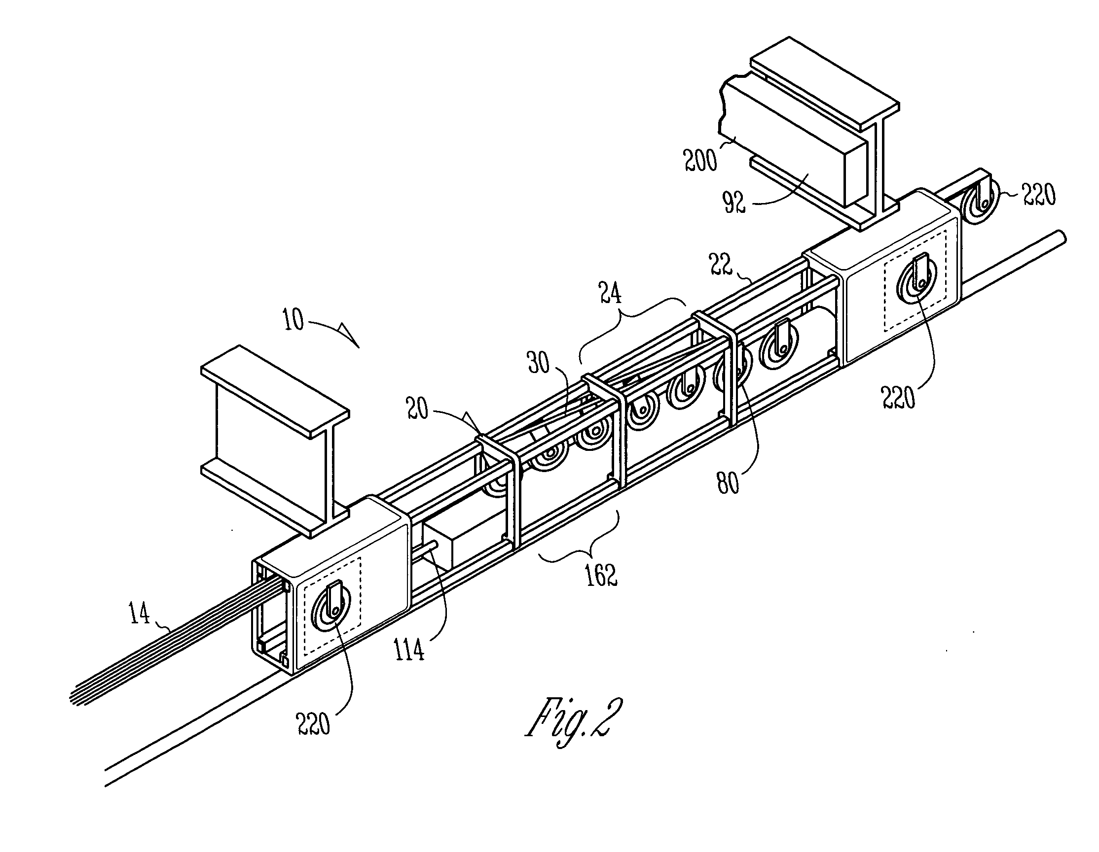
[0035]Referring to FIG. 1, the present lift assembly 10 is employed to selectively raise, lower and locate a batten 12 relative to a building or surrounding structure. Preferably, the lift assembly 10 moves a connected batten 12 between a lowered position and a raised position.

[0036]Although the term “batten” is used in connection with theatrical and staging environment, including scenery, staging, lighting as well as sound equipment, it is understood the term encompasses any load connectable to a windable cable.

[0037]The term “cable” is used herein to encompass any wire, metal, cable, rope, wire rope or any other generally inelastic windable material.

[0038]The term “building” is used to encompass a structure or facility to which the lift assembly is connected, such as but not limited to, performance venues, theaters, arenas, concert halls, auditoriums, schools, clubs, educational institutions, stages, convention centers, television studios showrooms and places of religious gatherin...


PUM


Abstract

A lift assembly having a drum rotatably mounted to a frame and linearly translatable with respect to one or more portions of the frame. A plurality of head blocks can be connected to the frame along a helical mounting path, wherein linear translation of the drum during takeoff or take-up can maintain a predetermined fleet angle between a take off point from the drum and the head block.

Description

CROSS-REFERENCE TO RELATED APPLICATIONS[0001]This application is a continuation of U.S. patent application Ser. No. 11 / 185,997 filed Jul. 20, 2005, which is a divisional of U.S. patent application Ser. No. 10 / 717,886 filed Nov. 20, 2003, now abandoned, which is a continuation-in-part of U.S. patent application Ser. No. 10 / 274,725 filed Oct. 19, 2002, now U.S. Pat. No. 6,988,716, which is a continuation-in-part of U.S. patent application Ser. No. 10 / 273,285 filed Oct. 17, 2002, now U.S. Pat. No. 6,691,986, which is a divisional of U.S. patent application Ser. No. 09 / 627,537 filed Jul. 28, 2000, now U.S. Pat. No. 6,634,622, the specifications of which are herein incorporated by reference in their entirety.[0002]This application is also related to U.S. application Ser. No. 10 / 690,132 filed Oct. 21, 2003, now U.S. Pat. No. 6,889,958, U.S. application Ser. No. 10 / 813,424 filed Mar. 29, 2004, now U.S. Pat. No. 6,997,442, U.S. application Ser. No. 11 / 463,823 filed Aug. 10, 2006, now U.S. P...

Claims


Application Information

Patent Timeline
Patent Type & Authority Applications(United States)
IPC IPC(8): B66D1/12A63J1/02B66D1/00B66D1/14B66D1/39B66D5/22
CPCA63J1/028B66D1/00B66D1/36B66D5/22B66D1/39
Inventor HOFFEND, JR., DONALD A.
Owner ELECTRONIC THEATRE CONTROLS
Why Eureka
Try Eureka