Method and apparatus for a down hole blow out preventer

Active Publication Date: 2019-10-22
SOKOLOW MARK TERRY
View PDF3 Cites 0 Cited by
  • Summary
  • Abstract
  • Description
  • Claims
  • Application Information

AI Technical Summary

Benefits of technology

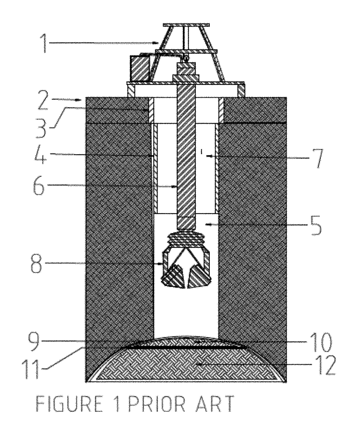
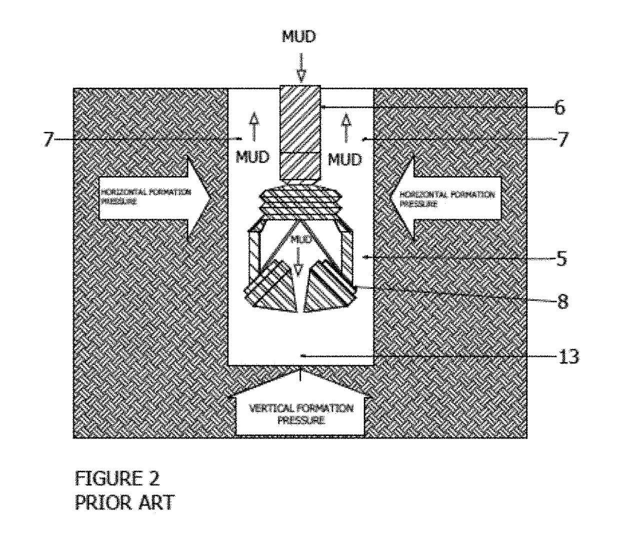
[0002]This invention is customized as to when the drilling operator is about to break into the seal or go into a formation which has unexpected pore pressures or fracture gradients. The seal is the impermeable rock barrier, under which the oil and/or gas is trapped. Once this seal is pierced, oil and/or gas can flow up through the well bore to the surface. Nevertheless, it is usually only estimated as to the exact depth, thickness and width of the seal as well as the vertical pressure thereunder. Thus, it can pose a danger to the drilling operator who is managing the pressures of the drilling operation who wishes to avoid a blowout. Also, petroleum engineers drill within a safety margin marked by an estimated pore pressure and by an estimated fracture gradient, with the weight of the mud (drilling fluid) and the frictional pressure of the drilling itself acting as to balance the pressure. If the mud weight and frictional pressure are too low, there could be a kick in that the pore pressure of the adjacent formation would exceed it. If the mud weight and frictional pressure are too high, it could exceed the fract

Problems solved by technology

Thus, it can pose a danger to the drilling operator who is managing the pressures of the drilling operation who wishes to avoid a blowout.
If the mud weight and frictional pressure are too low, there could

Method used


Image

  • Method and apparatus for a down hole blow out preventer
  • Method and apparatus for a down hole blow out preventer
  • Method and apparatus for a down hole blow out preventer

Examples


Embodiment Construction

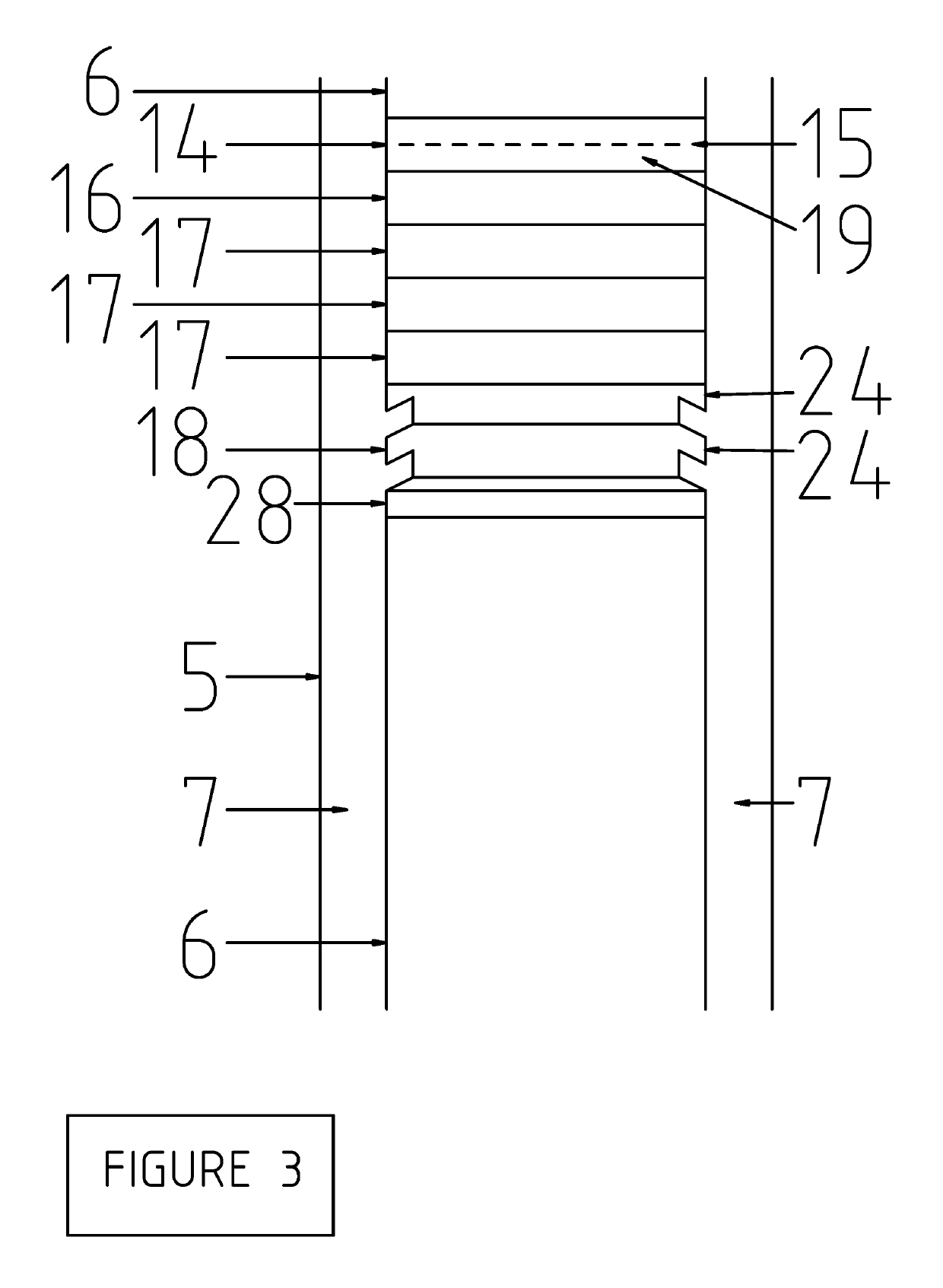
[0051]The inventor's first technique is designed to work as an automatic safety mechanism in the form of an automatic downhole blow out preventer that will be automatically activated when the safety threshold pressure is reached. In other words, a kick is occurring, mud, cuttings and formation fluid are coming up the annulus at a pressure and speed that can possibly cause a blow out if the mud, cuttings and formation fluid are not inhibited or blocked at an early stage. If the blow out pressure is determined hypothetically at 4000 psi, the safety threshold pressure could be set at 3600 psi. The number of pegs has hypothetically already been set around the grooved section of drill string at degree intervals of 0, 45, 90, 135, 180, 225, 270 and 315 degrees. The height of the pegs can be adjusted so that the pressure deflector ring is not released or able to bypass the pegs until the 3600 psi (pounds per square inch) is reached. Once the 3600 psi is reached, the external pressure defle...


PUM


Abstract

The invention is a method and apparatus, automatic down hole blow out preventer wherein external elastomer rings are placed on the exterior of a grooved section of drill pipe. Below the external elastomer rings is an external pressure deflector ring, which is designed to be lifted up in a kick. When a kick occurs, the increased pressure will force the external pressure deflector ring up, causing the external elastomer rings to flip up and out as to inhibit or block the further flow of fluid up the annulus.

Description

[0001]I hereby claim the benefit of a Provisional patent application filed on May 18, 2016 (Application No. 62 / 392,053).BACKGROUND AND SUMMARY OF THE INVENTION[0002]This invention is customized as to when the drilling operator is about to break into the seal or go into a formation which has unexpected pore pressures or fracture gradients. The seal is the impermeable rock barrier, under which the oil and / or gas is trapped. Once this seal is pierced, oil and / or gas can flow up through the well bore to the surface. Nevertheless, it is usually only estimated as to the exact depth, thickness and width of the seal as well as the vertical pressure thereunder. Thus, it can pose a danger to the drilling operator who is managing the pressures of the drilling operation who wishes to avoid a blowout. Also, petroleum engineers drill within a safety margin marked by an estimated pore pressure and by an estimated fracture gradient, with the weight of the mud (drilling fluid) and the frictional pre...

Claims


Application Information

Patent Timeline
IPC IPC(8): E21B33/10E21B21/10E21B34/08E21B33/12E21B33/126E21B33/06
CPCE21B33/06E21B33/12E21B33/126E21B33/10E21B34/08E21B21/103
Inventor SOKOLOW, MARK TERRY
Owner SOKOLOW MARK TERRY
Why Eureka
Try Eureka