Conveyor system with diverting track network

a technology of conveyor system and track network, which is applied in the direction of conveyor parts, transportation and packaging, packaging, etc., can solve the problems of increasing speed, reducing conveyor speed, and reducing the space of diverter shoes, so as to reduce the impact of diverter shoes, reduce the amount of spacing, and reduce the effect of conveyor speed

Inactive Publication Date: 2005-08-02
DEMATIC
View PDF14 Cites 26 Cited by
  • Summary
  • Abstract
  • Description
  • Claims
  • Application Information

AI Technical Summary

Benefits of technology

[0007]Accordingly, the present invention provides a sortation system which mitigates a number of the above-discussed difficulties. The sortation system is designed to lessen the impact of the diverter shoes against articles without having to reduce the conveyor speed or u

Problems solved by technology

Such spacing, however, often leaves little room for the diverter switches.
Diverting the shoes at too steep of an angle, however, can cause difficulties as will be set forth in more detail below.
Increasing the speed of the conveyor, however, can create other difficulties.
If this lateral speed gets too great, however, the diverter shoes may impinge the package with such force that the package is toppled, knocked backwards on the conveyor, knock

Method used


Image

  • Conveyor system with diverting track network
  • Conveyor system with diverting track network
  • Conveyor system with diverting track network

Examples


Embodiment Construction

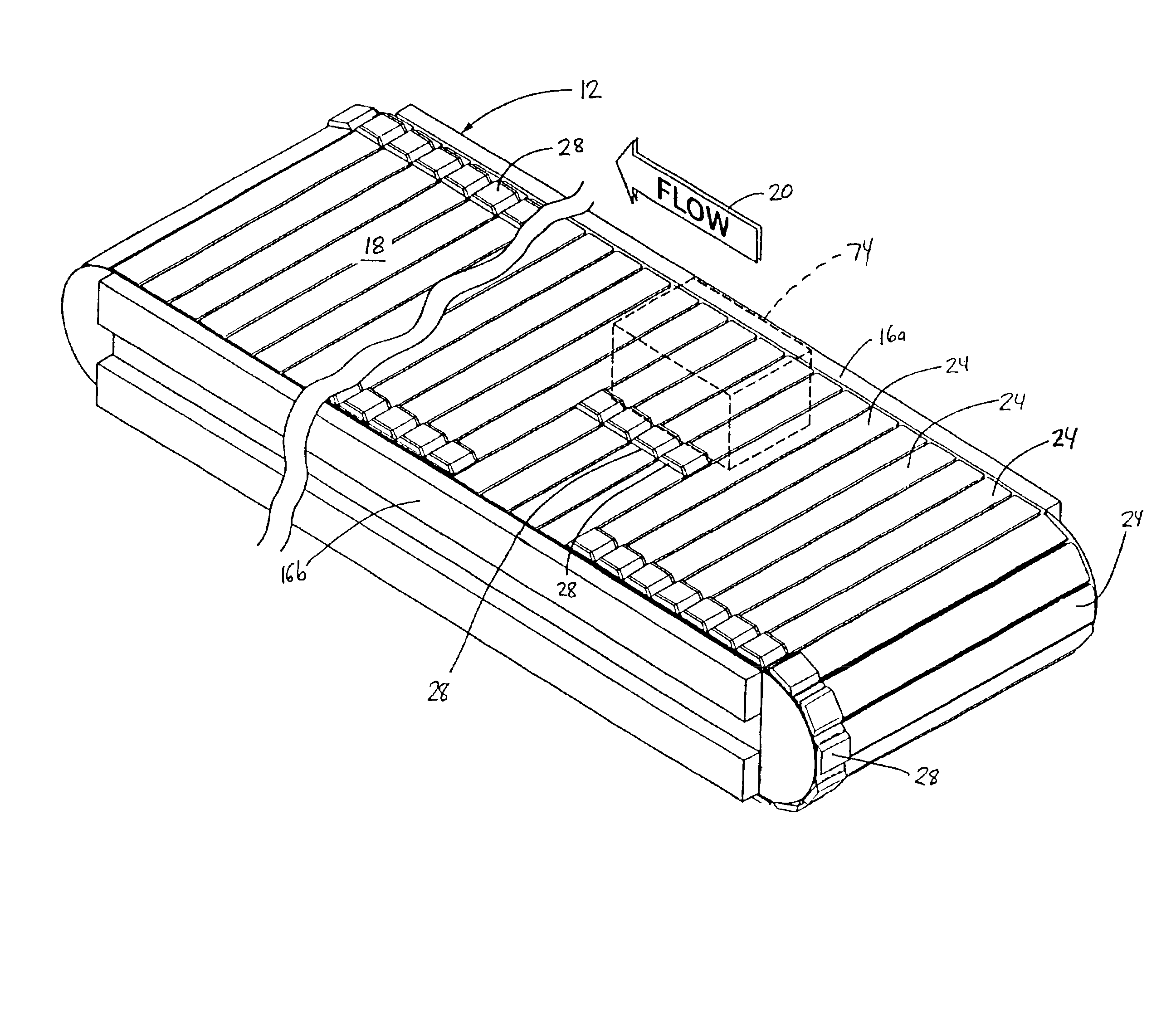
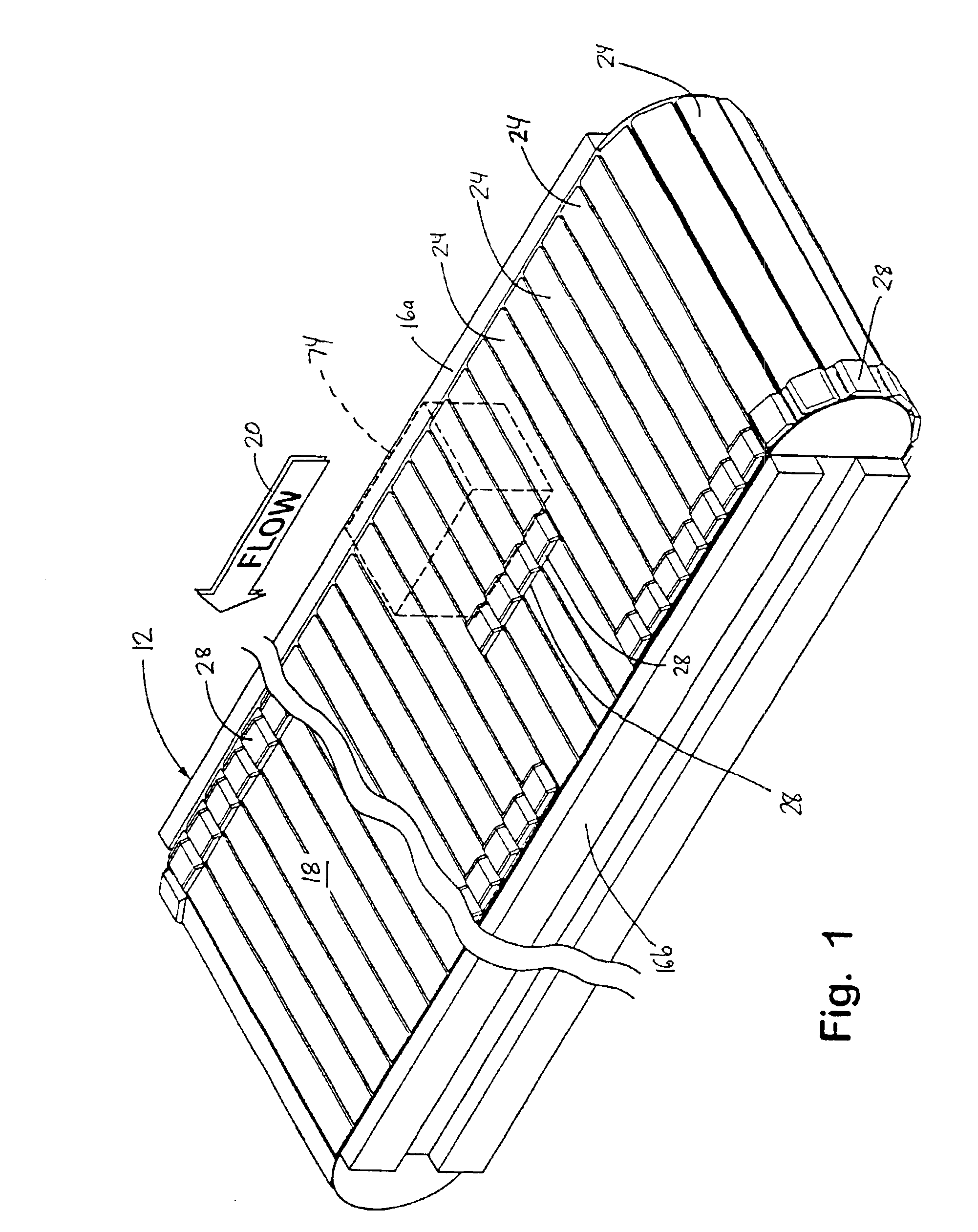
[0027]The present invention will now be described wherein the reference numerals in the following written description correspond to like-numbered elements in the several drawings. A sortation conveyor 12 is depicted in FIG. 1. Sorter 12 is illustrative of the types of conveyor sorters to which the various aspects of the present invention finds application. Conveyor 12 includes a conveying surface 18 defined by a series of surface members 24 that extend between sides 16a and b of sorter 12. Surface members 24 move in a direction of conveyance 20, and thereby carry articles 74 in the same direction. When articles, such as an article 74, are to be diverted off of conveyor 12 and onto one or more branch conveyors 14 (FIG. 6), a plurality of pusher shoes 28 are diverted out of their longitudinal flow path and caused to travel transversely across conveying surface 18. These shoes 28 impact the article and push it off of conveyor 12 onto the appropriate take-away conveyor 14.

[0028]An examp...


PUM


Abstract

A diverting assembly for diverting articles from a conveying surface includes a plurality of movable pushers that are associated with the conveying surface and adapted to move transversely across the conveying surface. A plurality of diverting tracks are configured to guide selected ones of the movable pushers across the conveying surface. A plurality of diverters are adapted to selectively divert at least one movable pusher along the diverting tracks when activated into a diverting state. The diverting tracks may include segments that are oriented at different angles with respect to each other. A controller may select a subset of at least two diverters from the plurality of diverters and activate them into the diverting state. The activation of the diverters may be simultaneous, or the downstream diverter may be activated prior to the upstream diverter being activated.

Description

CROSS-REFERENCE TO RELATED APPLICATIONS[0001]This application claims priority to U.S. Provisional Application Ser. No. 60 / 397,885, filed Jul. 23, 2002, entitled CONVEYOR SYSTEM WITH DIVERTING TRACKS, and U.S. Provisional Application Ser. No. 60 / 343,708, filed Nov. 1, 2001, entitled CONVEYOR SYSTEM WITH DIVERTING TRACK NETWORK, the disclosures of which are hereby incorporated herein by reference.BACKGROUND OF THE INVENTION[0002]This invention relates generally to conveyor diverting systems, and more particularly to conveyor diverting systems having an endless conveying surface composed of multiple surface members, each one or group of adjacent ones mounted with a laterally movable shoe capable of diverting packages or other articles from the conveying surface by pushing laterally against the articles as they move down the conveyor. Such lateral pushing diverts a package from a main conveyor to an adjacent branch conveyor, or other receiving structure.[0003]Conveyor diverting systems ...

Claims


Application Information

Patent Timeline
IPC IPC(8): B65G47/84B65G43/08B65G47/46
CPCB65G47/844B65G2207/36
Inventor VEIT, FRANK W.
Owner DEMATIC
Why Eureka
Try Eureka