Mounting device for a flat screen display panel

a technology for mounting devices and flat screen displays, which is applied in the direction of lightening support devices, washstand accessories, scaffold accessories, etc., can solve the problems of increasing weight, difficult to appreciate the weight involved in many of today's flat screen displays, and current flat panel displays can be quite heavy, so as to achieve the effect of convenient handling

Inactive Publication Date: 2005-08-02
GAMBER JOHNSON
View PDF24 Cites 134 Cited by
  • Summary
  • Abstract
  • Description
  • Claims
  • Application Information

AI Technical Summary

Benefits of technology

[0009]The preferred embodiments of the present invention provide a mounting device for a flat screen display panel that can easily be handled by a single installer and can conform to a plurality of mounting configurations corresponding to different display panels. According to one embodiment, a first mounting plate is secured to a support surface, such as a wall. A first mounting arm is secured to a display panel, and has a pivotally attached hook configured to engage the first mounting plate. The mounting arm then engages the mounting plate and the display panels weight is thereby supported by the mounting plate and mounting arm. The mounting plate and mounting arm cooperate to enable lateral horizontal adjustment of the display panel after it is secured in its vertical position, and the pivoting nature of the mounting arm allows the display panel to be adjusted in a pivotal direction about a horizontal axis.
[0011]The hook portions of the mounting arms are engaged with the upper mounting plate, and a resting portion of each mounting arm is engaged with the lower mounting plate. The pivotal nature of the hook portions allows the display panel to be pivotally adjusted about a horizontal axis. Furthermore, the hook portions and resting portions allow the display panel to be adjusted to a desired horizontal position by sliding the hook portions and resting portions laterally with respect to the mounting plates.

Problems solved by technology

Current flat panel displays can be quite heavy, with the weight increasing as the display size increases.
This can be a difficult task appreciating the weight involved in many of today's flat panel displays.
In addition to weight, an additional drawback results from the fact that today's flat panel display devices are not consistent in their location of mounting holes or mounting hardware, and thus, a plurality of different mounting devices are required to conform to the individual panel to be mounted.

Method used


Image

  • Mounting device for a flat screen display panel
  • Mounting device for a flat screen display panel
  • Mounting device for a flat screen display panel

Examples


Embodiment Construction

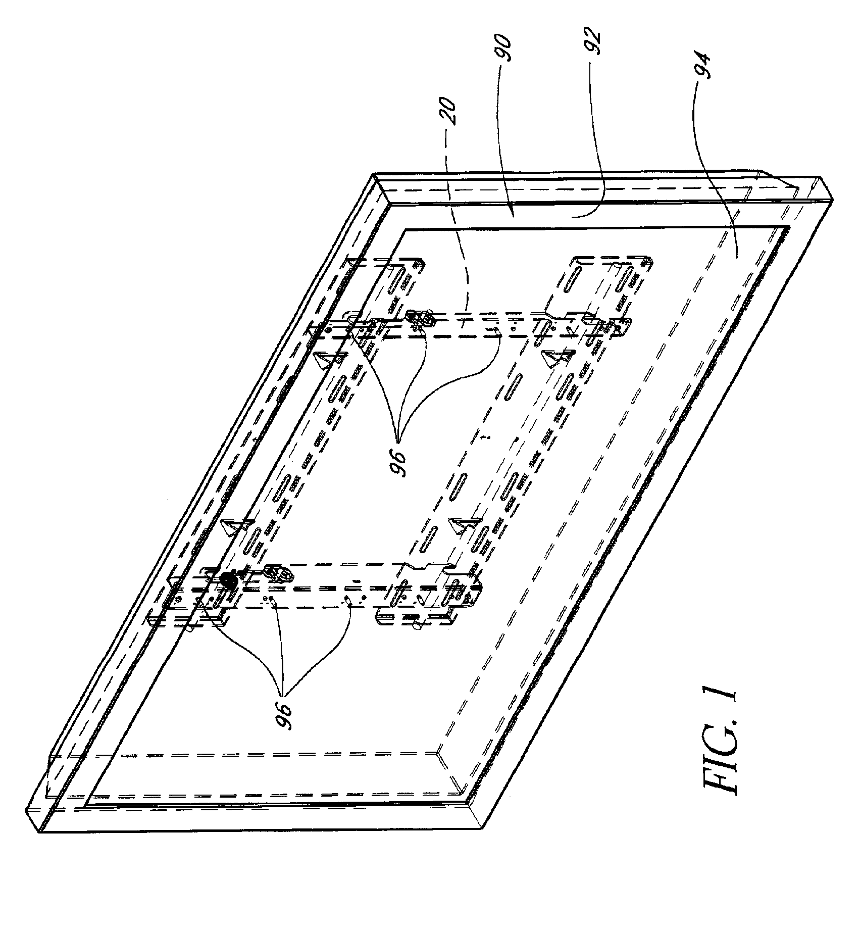
[0030]Referring to FIGS. 1, 11, and 12 there is shown one embodiment of a wall mounting device 20 of the present invention for use in conjunction with the flat screen display panel 90. It should be noted that the term “wall” as used herein encompasses any substantially vertical surface suitable for mounting a display panel thereon, and should not limit the term to its common meaning.

[0031]The embodiments described below enable low-profile mounting devices for the panel display 90 that are easy to use and greatly facilitate mounting of the panel display to the desired wall position.

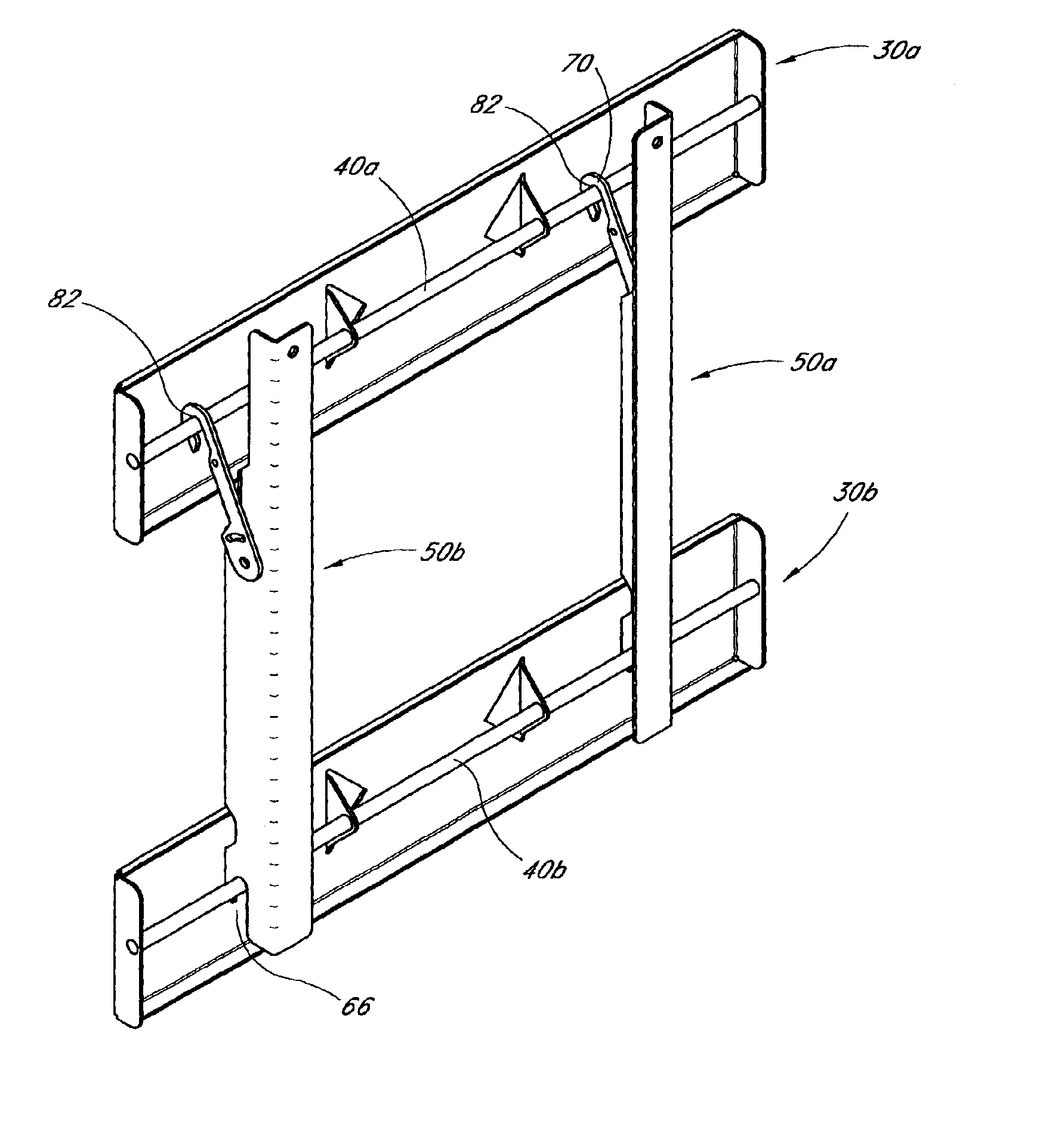
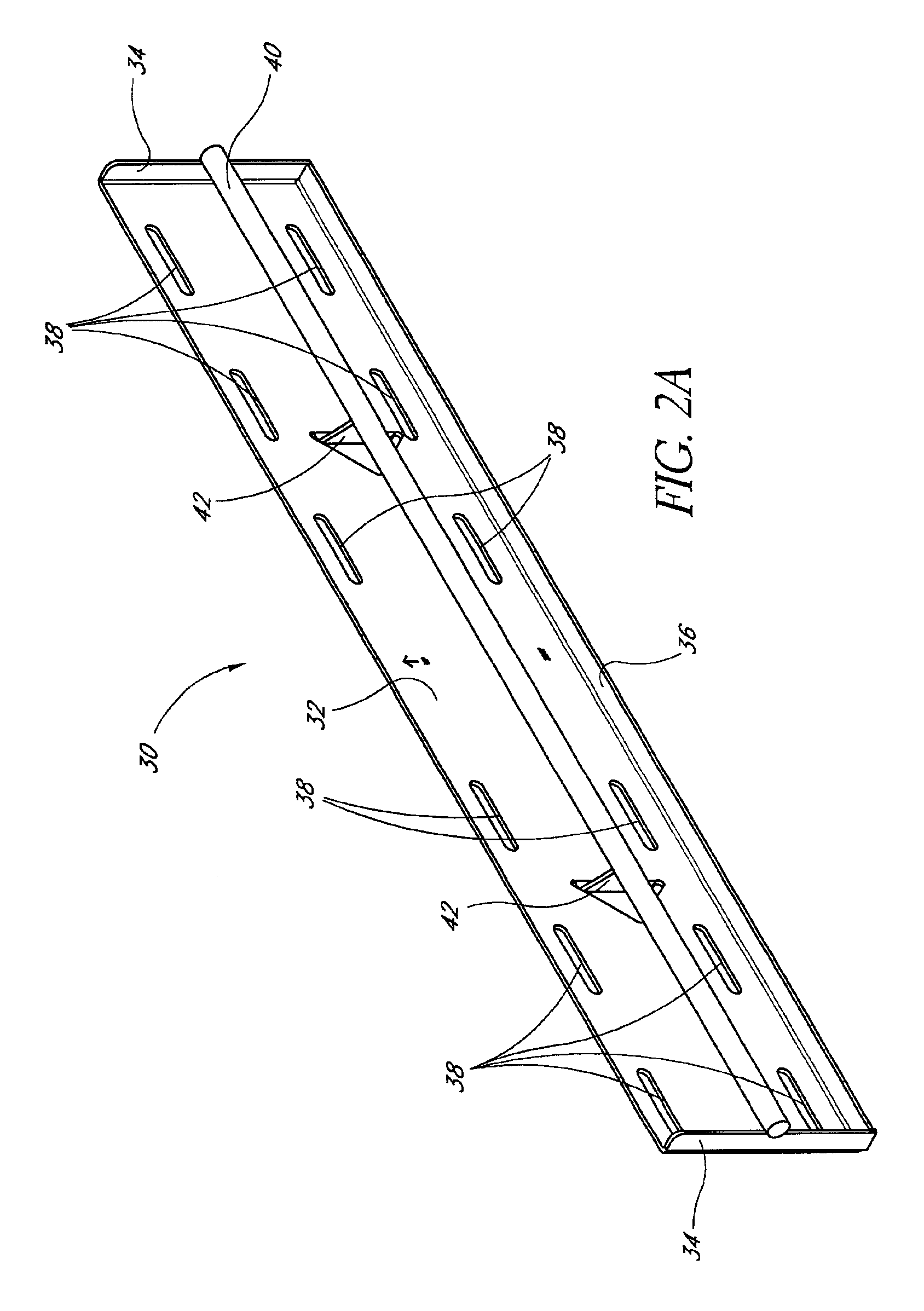
[0032]FIGS. 2a and 2b each show different embodiments of a wall bracket 30. Although a single such bracket is shown in each Figure, pairs of such wall brackets 30 are advantageously used to securely hold a display panel. A wall bracket 30 generally has a mounting surface 32 for contacting the desired surface for mounting the display panel. The mounting surface 32 is preferably bounded on two opposing later...


PUM


Abstract

A mount for attaching a flat screen display panel is disclosed in which a wall bracket is attached to a support surface, a panel bracket is secured to a display panel, and the two brackets then cooperate to securely affix the display panel to the support surface while allowing subsequent lateral and pivotal adjustment.

Description

BACKGROUND OF THE INVENTION[0001]1. Field of the Invention[0002]The present invention relates generally to a mounting device for a flat screen display panel. More specifically, a mounting device for a flat screen display panel that allows the display screen to be adjusted both laterally and pivotally subsequent to mounting is disclosed.[0003]2. Description of the Related Art[0004]Flat screen displays, such as plasma televisions, thin film transistor (“TFT”) displays and the like, are progressively gaining popularity throughout the marketplace. As a result, they are regularly showing up in a wide variety of viewing areas ranging from boardrooms to family rooms.[0005]This recent proliferation has resulted in many different mounts and mounting techniques. There are several different ways to mount a flat panel display including hanging ceiling supports, floor stands, and wall mounts. Current flat panel displays can be quite heavy, with the weight increasing as the display size increases...

Claims


Application Information

Patent Timeline
Patent Type & Authority Patents(United States)
IPC IPC(8): F16M13/02F16M11/02F16M11/10
CPCF16M11/10F16M13/02F16M2200/024Y10S248/917
Inventor DOZIER, LEONARD
Owner GAMBER JOHNSON
Why Eureka
Try Eureka