Combination voltage detector and LED flashlight

a voltage detector and led flashlight technology, applied in the field of voltage detectors, can solve the problems of difficult to see wires and terminals, relatively low storage capacity of watch batteries, and severe limits to their life span

Inactive Publication Date: 2005-08-02
CHUN JAMES K
View PDF6 Cites 36 Cited by
  • Summary
  • Abstract
  • Description
  • Claims
  • Application Information

AI Technical Summary

Problems solved by technology

Unfortunately, watch batteries have relatively low storage capacity which severely limits their life spans.
Many electricians work in dark environments that make it difficult to see wires and terminals.

Method used


Image

  • Combination voltage detector and LED flashlight
  • Combination voltage detector and LED flashlight
  • Combination voltage detector and LED flashlight

Examples


Embodiment Construction

)

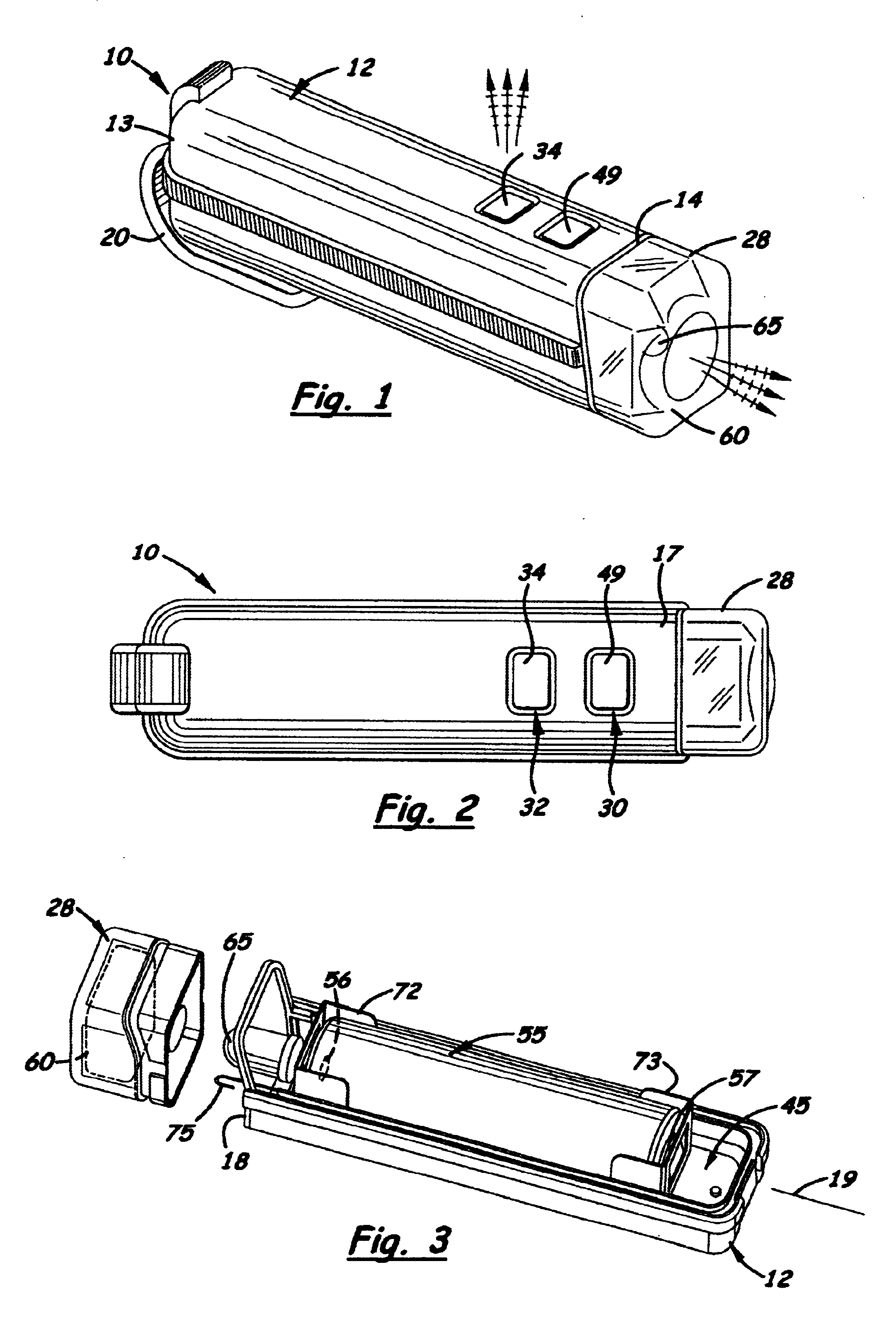
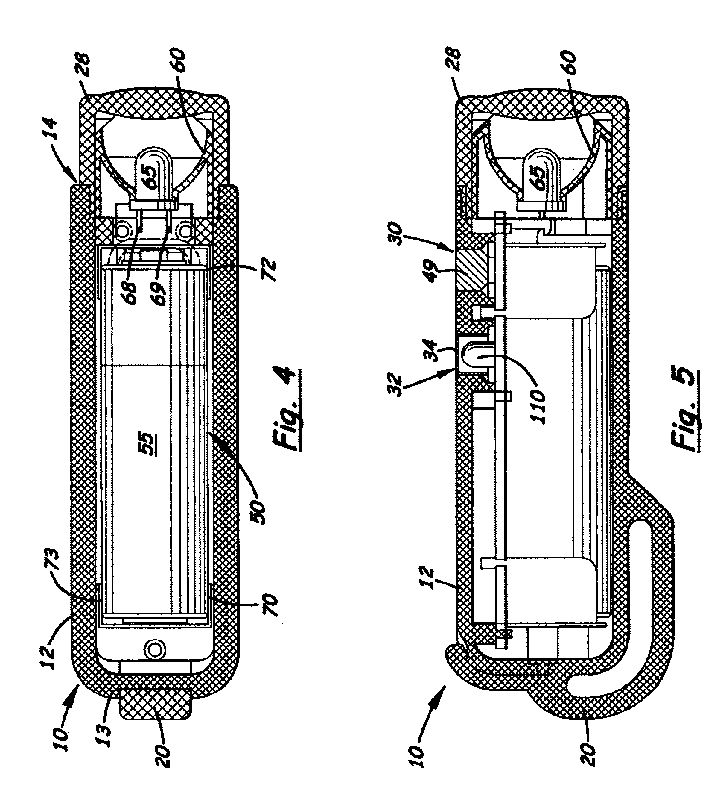
[0021]Referring to the accompanying Figs., there is shown and described a combination voltage detector and LED flashlight, generally referred to as device 10. The device 10 includes an elongated hollow body 12, with a closed end 13 and a transparent main lens 28 that attaches over an open end 14. The body 12, which is made of a clear or colored plastic or similar material, is made of two half components 17, 18 that snap together along the body's central longitudinal axis 19. Formed on the closed end 13 of the body 12 is an optional key ring 20.

[0022]As mentioned above, attached over the open end 14 of the body 12 is a main lens 28 made of plastic or similar material. Located inside the main lens 28 is a transversely aligned chrome plated reflector 60 which acts as a sensor probe (hereinafter referred to as reflector / sensor probe 60) for the voltage detector circuit 100 discussed further below.

[0023]As shown in FIGS. 1 and 2, formed on the outer surface of the body 12 are two holes ...


PUM


Abstract

A combination electric field sensor and a flashlight with at least one main LED disclosed that uses a voltage multiple circuit that enables the use of a single AA or AAA battery. The voltage multiple circuit raises the battery voltage from 1.5 volts to approximately 5 volts required to sufficiently energize the main LED. The device includes a voltage detector circuit with a sensor probe which detects the presence of an electric field when the device is placed adjacent thereto and a second LED. The second LED is connected to the voltage detector circuit and designed to flash when placed against an electric field.

Description

BACKGROUND OF THE INVENTION[0001]1. Field of the Invention[0002]The present invention relates to voltage detectors, and more particularly, to voltage detectors that include a flashlight.[0003]2. Description of the Related Art[0004]Electricians commonly use a handheld, lightweight AC voltage detector to locate the hot, neutral and ground wires and terminals. An example of such a detector is sold by Fluke (Model Number 1AC and 1LAC) which is relatively small and fits into a shirt pocket. During use, the tip of the sensor glows red if a voltage is detected in a wire or terminal.[0005]In order to make them small and lightweight for transport in a pocket, the detectors often use watch batteries. Unfortunately, watch batteries have relatively low storage capacity which severely limits their life spans. To prevent electrical shocks that may occur by using a detector with discharged batteries, many detectors include test buttons that are pressed to determine if the batteries are sufficientl...

Claims


Application Information

Patent Timeline
Patent Type & Authority Patents(United States)
IPC IPC(8): F21L4/00
CPCF21L4/005G01R1/06788F21Y2101/02G01R19/155F21Y2115/10
Inventor CHUN, JAMES K.
Owner CHUN JAMES K
Why Eureka
Try Eureka