Voltage sensor

a voltage sensor and voltage sensor technology, applied in the field of voltage sensors, can solve the problems of large equipment cost, large equipment cost, and large equipment maintenance costs, and achieve the effect of significantly reducing deficiencies

Inactive Publication Date: 2002-04-30
ALSTOM TECH LTD
View PDF18 Cites 36 Cited by
  • Summary
  • Abstract
  • Description
  • Claims
  • Application Information

AI Technical Summary

Benefits of technology

The present invention reduces significantly the deficiencies inherent to the existing high-voltage sensor technology.
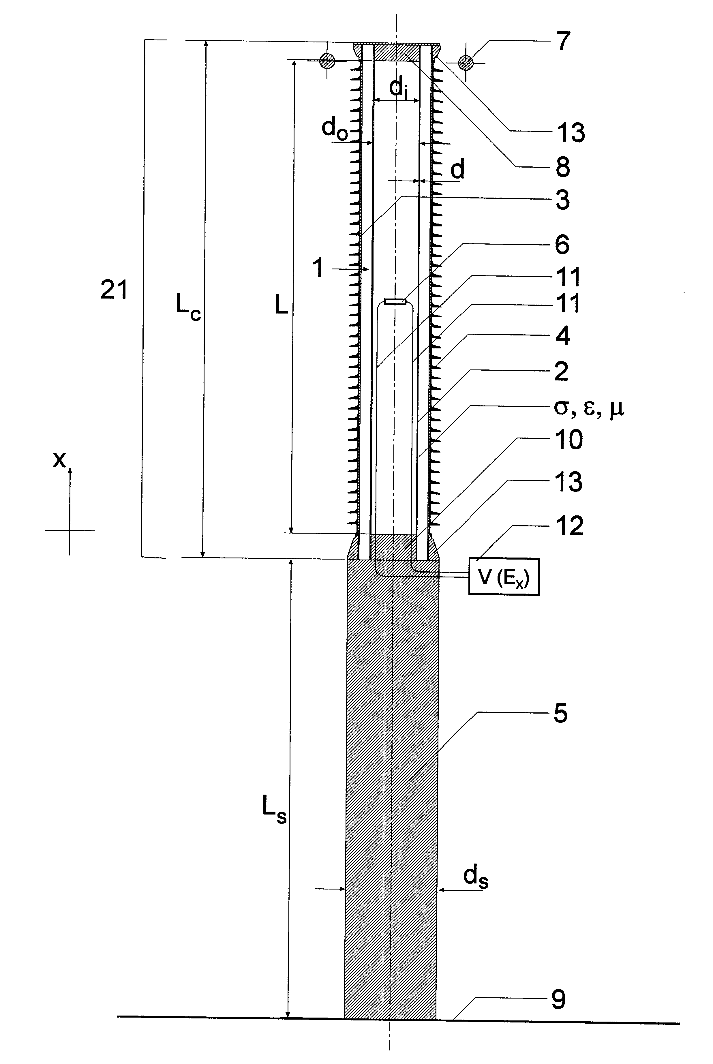
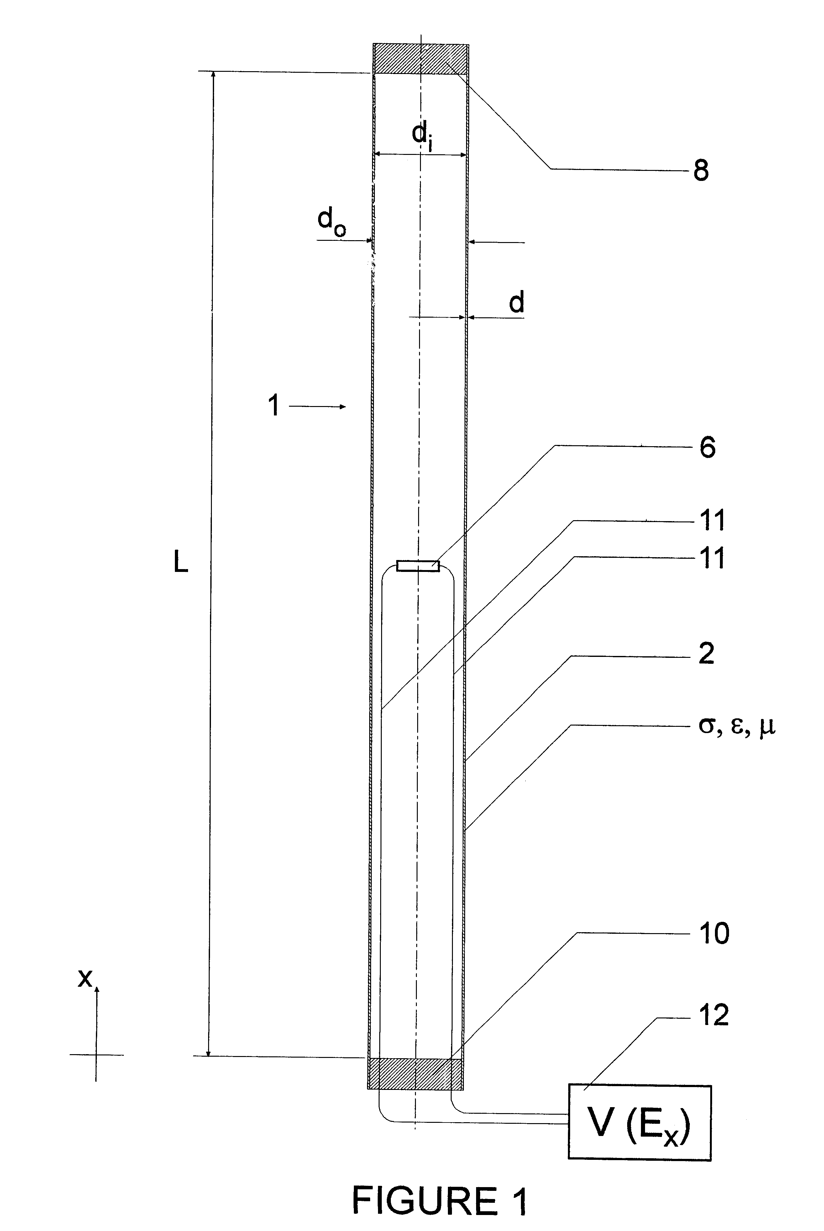
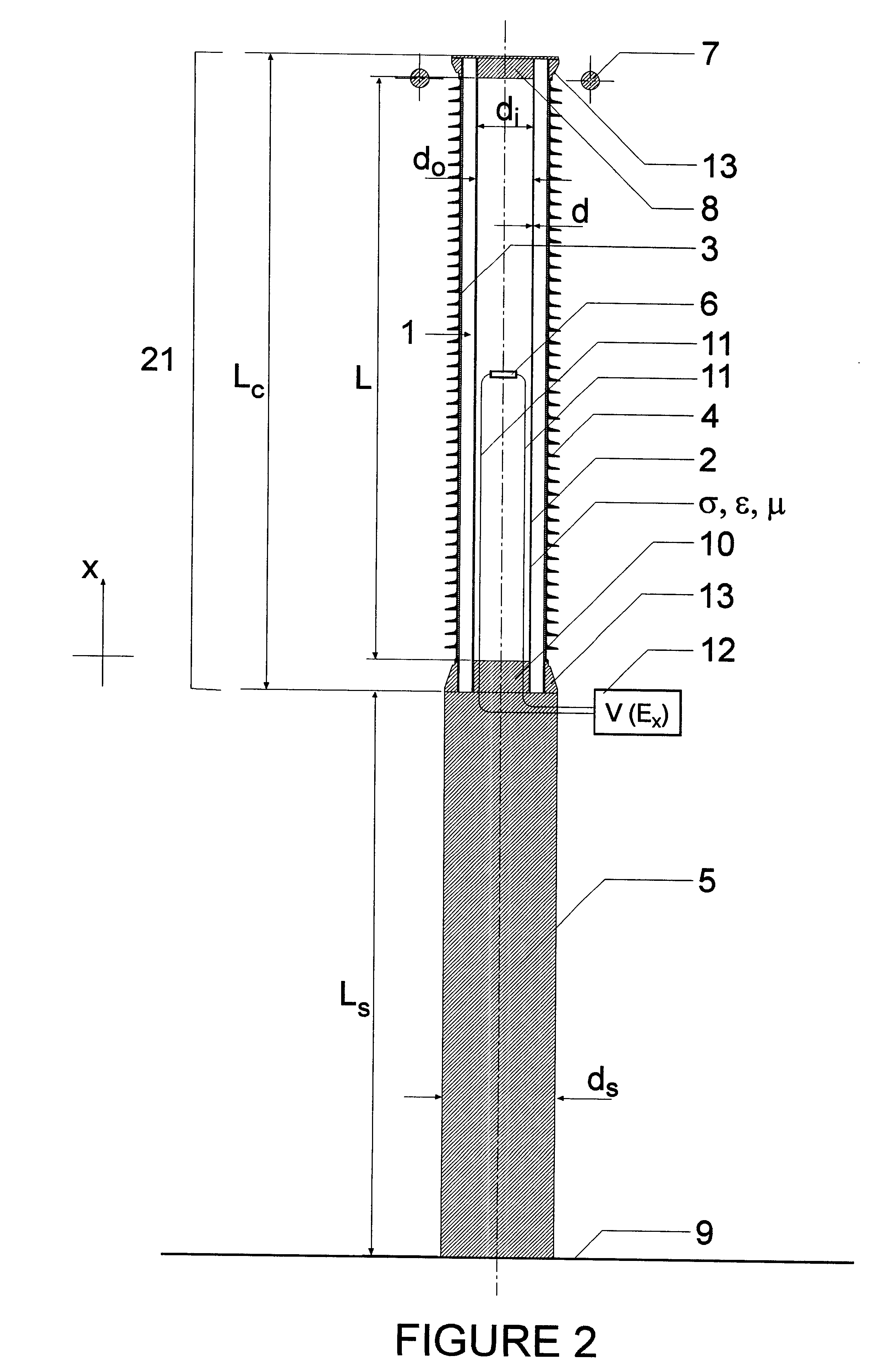
Generally for any isolating-section 2 consisting of a material of fixed electrical properties a shorter length L and / or greater cross-sectional area A of the isolating-section 2 (see FIGS. 1 and 2) gives a smaller impedance and therefore a larger Y. Also, generally for any isolating-section 2 of fixed geometry a higher conductivity .sigma., higher permittivity .epsilon., and / or lower permeability .mu. of the isolating-section 2 gives a larger Y. In practice, varying .sigma. as taught by the present invention allows great flexibility in achieving a desired Y. Still, the choice of values of parameters (1) through (5) depends on considerations such as the accuracy and safety requirements for the voltage sensor. Also, in accordance with the lumped admittance model and in order to reduce Y.sub.ie s, the high admittance material of the isolating-section 2 should be more centrally confined improving isolation of the field in the center from stray field effects.

Problems solved by technology

The first two sensors suffer from bandwidth restrictions, expensive failure, extensive maintenance, heavy weight, and output variations.
They also suffer from the need for substantial insulation that is both expensive and potentially hazardous to the environment (e.g oil and / or SF.sub.6 gas).
This shielding while effective requires the use of materials with high permittivities which are not always easy to obtain and generally are expensive and relatively heavy.
Use of these methods results in the existence of high electric field stresses that must be supported with special insulation such as SF.sub.6 gas.

Method used


Image

  • Voltage sensor
  • Voltage sensor
  • Voltage sensor

Examples


Embodiment Construction

EFSVT Test Simulations

In the following example, the performance of an EFSVT standoff (particularly the isolating-section 2 of the standoff 21) is described and evaluated by simulation. The EFSVT structure is shown in FIG. 2.

The particular standoff to be analyzed has a height L.sub.c =2245 mm and is supported on a grounded stand with height L.sub.s =2 m and diameter d.sub.s =400 mm. Also, it has a corona ring with inner diameter 539 mm and outer diameter 671 mm at the base of the top electrode. There are 45 rubber sheds; an outer fiberglass tube with inner diameter 300 mm and outer diameter 312 mm; an inner isolating-section 2, a tube with inner diameter d.sub.i =198 mm and outer diameter d.sub.o =206 mm; and an electrode-to-electrode spacing L=2070 mm. Here, various EFSVT examples are given having different inner tube resistances of infinity, 10.sup.12, 10.sup.9, 10.sup.8, 5.times.10.sup.7, and 10.sup.6.OMEGA.. The relative permittivities of the inner and outer tubes are 5 and the r...


PUM


Abstract

A voltage sensor for measuring the voltage on high voltage lines is formed by an electrically isolating-section of material with resistive shielding (RS) that structures the electric field generated by a voltage difference between the two ends of the isolating-section and provides shielding of the internal electric field from sources of electric field interference external to the voltage sensor. At least one electric field sensor is provided to sense the electric field in the isolating-section the output(s) of which is(are) used to infer the voltage difference.

Description

The present invention relates to a voltage sensor for measuring voltage and is particularly suitable for measuring high voltages such as on high-voltage power transmission lines.BACKGROUND TO THE INVENTIONThe list of known high-voltage voltage sensors includes inductive transformers, capacitive dividers or capacitive voltage transformers, and transducers using bulk-optic electric field sensors. The first two sensors suffer from bandwidth restrictions, expensive failure, extensive maintenance, heavy weight, and output variations. They also suffer from the need for substantial insulation that is both expensive and potentially hazardous to the environment (e.g oil and / or SF.sub.6 gas).Pockels cells are known devices that have been used for measuring voltage particularly high voltage, for example see U.S. Pat. No. 5,477,134 issued to H. Hamada and U.S. Pat. No. 5,731,579 issued to G. K. Woods. A preferred form of Pockels cell for use in the present invention is an integrated optics Pock...

Claims


Application Information

Patent Timeline
Patent Type & Authority Patents(United States)
IPC IPC(8): G01R15/24G01R15/14G01R1/02G01R1/18G01R19/00G01R15/20G01R15/06
CPCG01R1/18G01R15/247G01R15/144G01R19/0053
Inventor CHAVEZ, PATRICK PABLORAHMATIAN, FARNOOSHJAEGER, NICOLAS AUGUST FLEMINGYAKYMYSHYN, CHRISTOPHER PAUL
Owner ALSTOM TECH LTD
Why Eureka
Try Eureka