
Head protecting body for safety helmet and safety helmet having head protecting body

a head protection and safety helmet technology, applied in the direction of protective garments, hats, headwear caps, etc., can solve the problems of increasing difficult to reduce the hic, and the difficulty of reducing the maximum acceleration, so as to prevent the strength of the forehead region and reduce the maximum acceleration

Inactive Publication Date: 2005-08-09
SHOEI CO LTD
View PDF9 Cites 66 Cited by
  • Summary
  • Abstract
  • Description
  • Claims
  • Application Information

AI Technical Summary

Benefits of technology

[0020]It is, therefore, the main object of this invention to decrease both the maximum acceleration during an impact and the HIC effectively in the antecedent head protecting body while preventing the strength of the forehead region of the impact-on-the-head absorbing liner from decreasing more than necessary.
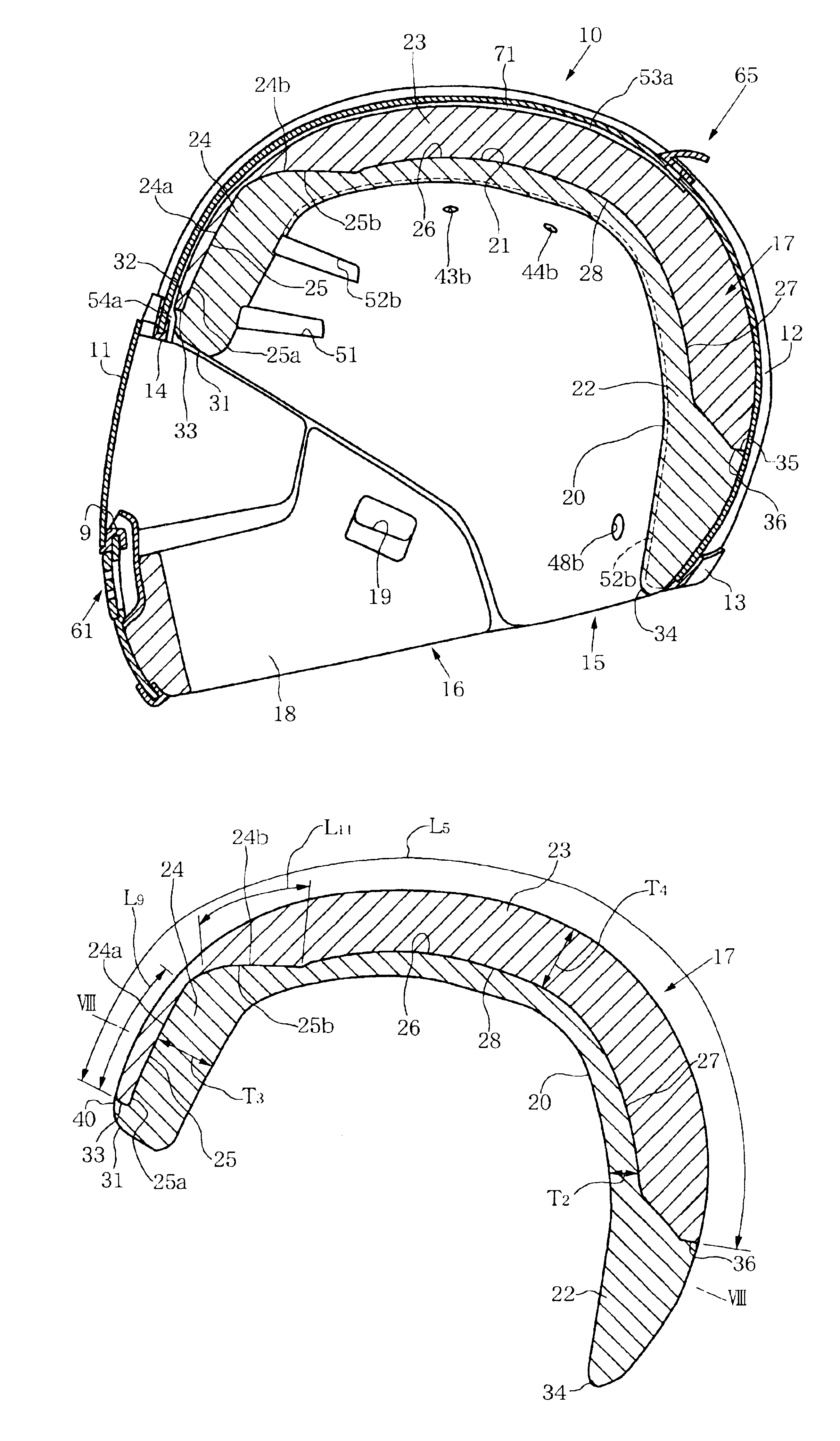
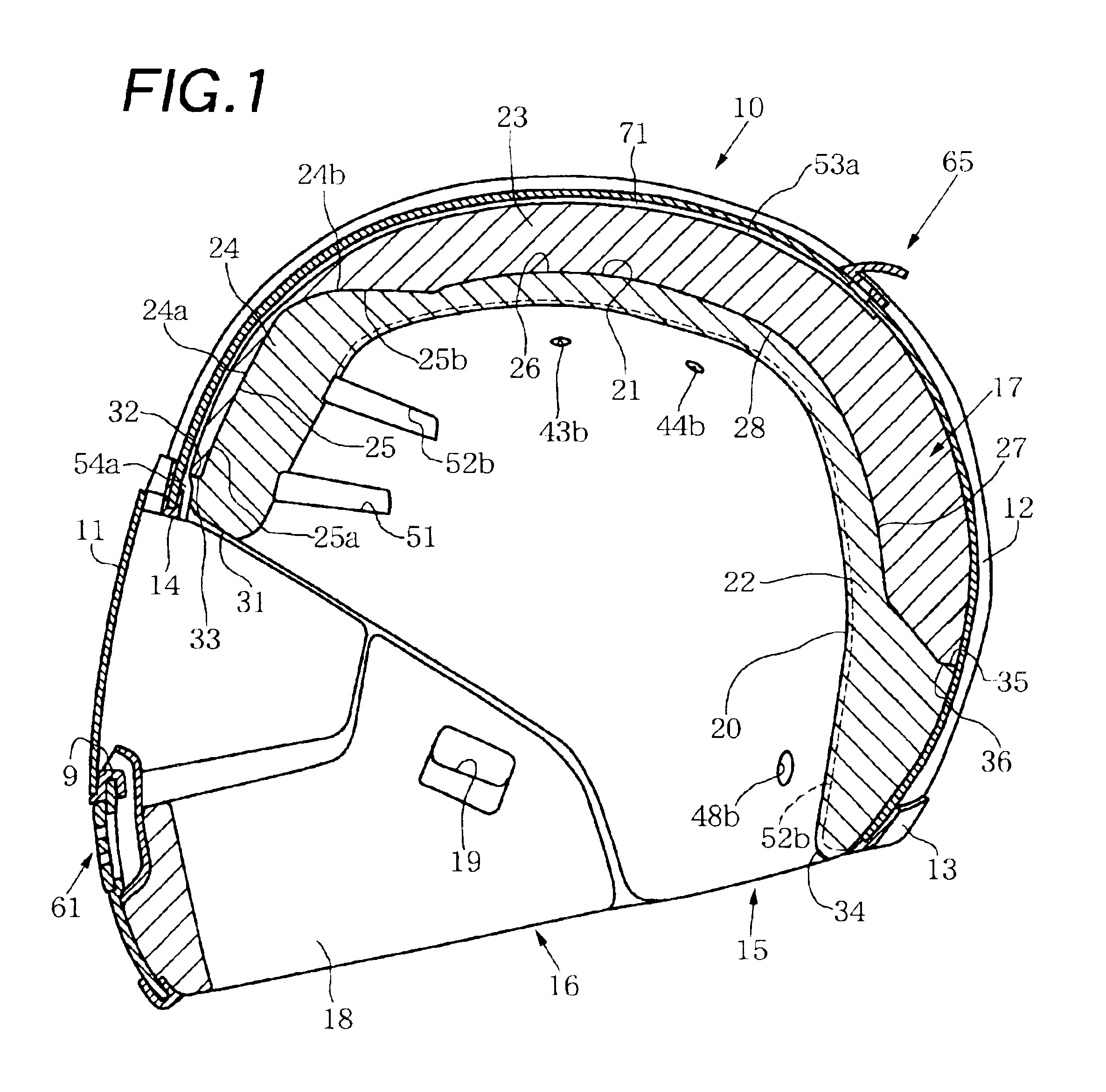
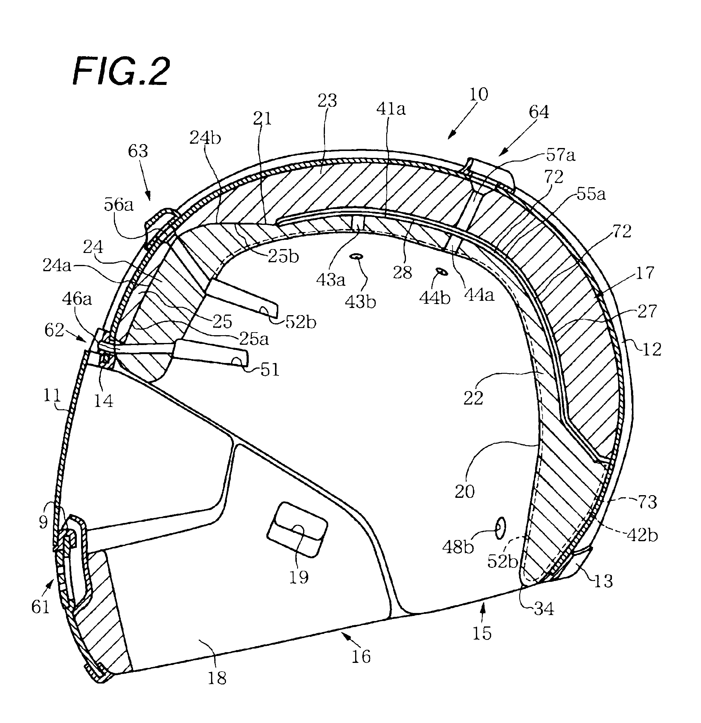
[0021]According to this invention, there is provided a head protecting body for a safety helmet, comprising an outer shell made of a rigid material and an impact-on-the-head absorbing liner arranged inside the outer shell, the impact-on-the-head absorbing liner comprising a first liner member, and a second liner member having a density lower than that of the first liner member and stacked on (i.e., overlapping with) the first liner member at least partially, wherein the first liner member comprises a swell for reinforcing at least one region of a forehead region, a left temple region, a right temple region and an occiput region in a stacking region (i.e., an overlapping region) with respect to the second liner member on a stacking surface side (i.e., an overlapping surface side) of the first liner member, the swell having a thickness larger than that of a portion of the first liner member which excludes the swell in the overlapping region, the second liner comprises a hollow having a shape substantially corresponding to the swell in a stacking region (i.e., an overlapping region) with respect to the first liner member, the hollow has a thickness smaller than that of a portion of the second liner member which excludes the hollow of the overlapping region, and the swell is fitted in the hollow. According to this invention with the above arrangement, the strength of that region of the impact-on-the-head absorbing liner which is reinforced by the reinforcing swell does not decrease very much. The outer shape of the impact-on-the-head absorbing liner deforms effectively by an impact, so that the impact energy is dispersed and absorbed effectively, and the thickness of the impact-on-the-head absorbing liner decreases effectively. Thus, the impact energy is absorbed effectively. Although the impact-on-the-head absorbing liner is not broken easily more than necessary near the reinforced region, both the maximum acceleration during the impact and the HIC can be decreased effectively.

Problems solved by technology

If, however, the thickness of the impact absorbing liner is merely increased, not only the maximum acceleration is not decreased sufficiently, but also it is particularly difficult to decrease the HIC.
As a result, the impact-on-the-head absorbing liner tends to be broken easily more than necessary near the forehead region.

Method used


Image

  • Head protecting body for safety helmet and safety helmet having head protecting body
  • Head protecting body for safety helmet and safety helmet having head protecting body
  • Head protecting body for safety helmet and safety helmet having head protecting body

Examples


first embodiment

1. First Embodiment

[0073]First, the first embodiment will be separated into items “(1) entire helmet”, “(2) impact-on-the-head absorbing liner” and “(3) ventilator mechanism” and will be described with reference to FIGS. 1 to 14.

(1) Entire Helmet

[0074]As shown FIGS. 1 and 2, a head protecting body 10 serves to form a full-face-type safety helmet. Accordingly, in addition to the head protecting body 10, the helmet has a pair of conventionally known left and right chin straps (not shown), the proximal ends of which are attached to the inner side of the head protecting body 10. As described above, the helmet can further have a conventionally known shield plate 11 for opening / closing a window opening 9. FIGS. 1 and 2 show the head protecting body 10 in a state wherein the wearer wearing the helmet is in an ordinary posture.

[0075]As shown in FIGS. 1 and 2, the head protecting body 10 is made up from a full-face-type outer shell 12 which constitutes the circumferential wall of the head pr...

second embodiment

2. Second Embodiment

[0125]The second embodiment of this invention shown in FIGS. 15 and 27 can have the same arrangement as that of the first embodiment of this invention except that the main liner member 22 of the first embodiment (see FIGS. 1 and 14) of this invention is altered to a composite main liner member (in other words, first liner member) 83 constituted by a main liner member main body (i.e., a single main liner member) 81 and a central auxiliary liner member (in other words, second auxiliary liner member) 82. In this case, the composite main liner member 83 of the second embodiment of this invention can have substantially the same shape as that of the main liner member 22 of the first embodiment of this invention except that it is constituted by the two liner members. The second embodiment of this invention can accordingly by substantially the same as the first embodiment of this invention except for the above differences and differences to be described later. Portions t...

third embodiment

3. Third Embodiment

[0142]The third embodiment of this invention shown in FIGS. 28 and 29 is obtained by reversing, in the first embodiment of this invention (see FIGS. 1 to 14), the positional relationship between the inner surface side and outer surface side of the main liner member 22, recess 21 and auxiliary liner member 23. Accordingly, in the third embodiment, in place of the outer recess 21 of the first embodiment, an inner recess (in other words, surface recess) 91 is formed in the inner surface of a main liner member 22. In the third embodiment, in place of the outer auxiliary liner member 23 of the first embodiment, an inner auxiliary liner member (in other words, second liner member) 92 is placed and fitted in the inner recess 91. The third embodiment of this invention can be substantially the same as the first embodiment of this invention except for the above differences and differences to be described later. Portions that are common to the first embodiment of this invent...


PUM


Abstract

A head protecting body for a safety helmet, in which a first liner member for an impact-on-the-head absorbing liner includes a swell for reinforcing at least one region of a forehead region, a left temple region, a right temple region and an occiput region in an overlapping region with respect to a second liner member having a density lower than that of the first liner member, on an overlapping surface side of the first liner member, and the second liner member includes a hollow having a shape substantially corresponding to the swell. According to this head protecting body, despite that the impact-on-the-head absorbing liner is not broken easily more than necessary near a region reinforced with the reinforcing swell, both the maximum acceleration during impact and an HIC can be decreased effectively.

Description

PRIORITY CLAIM[0001]This application claims the benefit of Japanese Patent Application No. 2002-234030, filed on Aug. 9, 2002.[0002]1. Technical Field[0003]This invention relates to a head protecting body for a safety helmet, which has an outer shell made of a rigid material and an impact-on-head absorbing liner arranged inside the outer shell, and a safety helmet having such a head protecting body.[0004]2. Background of the Invention[0005]A safety helmet such as a full-face-, jet-, or semi-jet-type helmet, which has a head protecting body and is to be worn on the head of a helmet wearer (to be merely referred to as a “wearer” hereinafter) such as the rider of a motor cycle to protect his / her head is conventionally known. The conventional full-face-, jet-, or semi-jet-type helmet usually has a head protecting body and a pair of left and right chin straps attached inside the head protecting body, and is typically formed in the following manner.[0006]More specifically, the head protec...

Claims


Application Information

Patent Timeline
IPC IPC(8): A42B3/12A42B3/04A42B3/28A42B3/06
CPCA42B3/128A42B3/28A42B3/06
Inventor TAKAHASHI, MASAMIUCHIYAMA, SHINICHI
Owner SHOEI CO LTD
Learn More