Terminal Box

a terminal box and box body technology, applied in the field of terminal boxes, can solve the problems of affecting the fixing strength the risk of lowering the fixing strength, and the risk of affecting the fixing of the backflow prevention diode to become unstabl

Active Publication Date: 2012-03-01
HOSIDEN CORP
View PDF5 Cites 22 Cited by
  • Summary
  • Abstract
  • Description
  • Claims
  • Application Information

AI Technical Summary

Benefits of technology

[0046]According to this configuration, the opposing sides of the rectangular lid are retained to the main body by the retention mechanisms, and when the internal pressure of the main body is increased, the sides of the lid which are not retained by the retention mechanisms, from among the transversal sides and

Problems solved by technology

In the conventional terminal box described above, the lead wire of the backflow prevention diode is soldered while the lead wire is placed on the planar terminal strip, and thus the solder is likely to spread to other parts along a plane of the terminal strip, and heat of the spread solder may involve a risk of an adverse influence on other parts (e.g. devices).
In addition, if the solder spreads to other parts and an amount of the solder becomes insufficient for an essential portion of the lead wire, there is a risk of lowering in a fixing s

Method used


Image

  • Terminal Box
  • Terminal Box
  • Terminal Box

Examples


embodiment 1

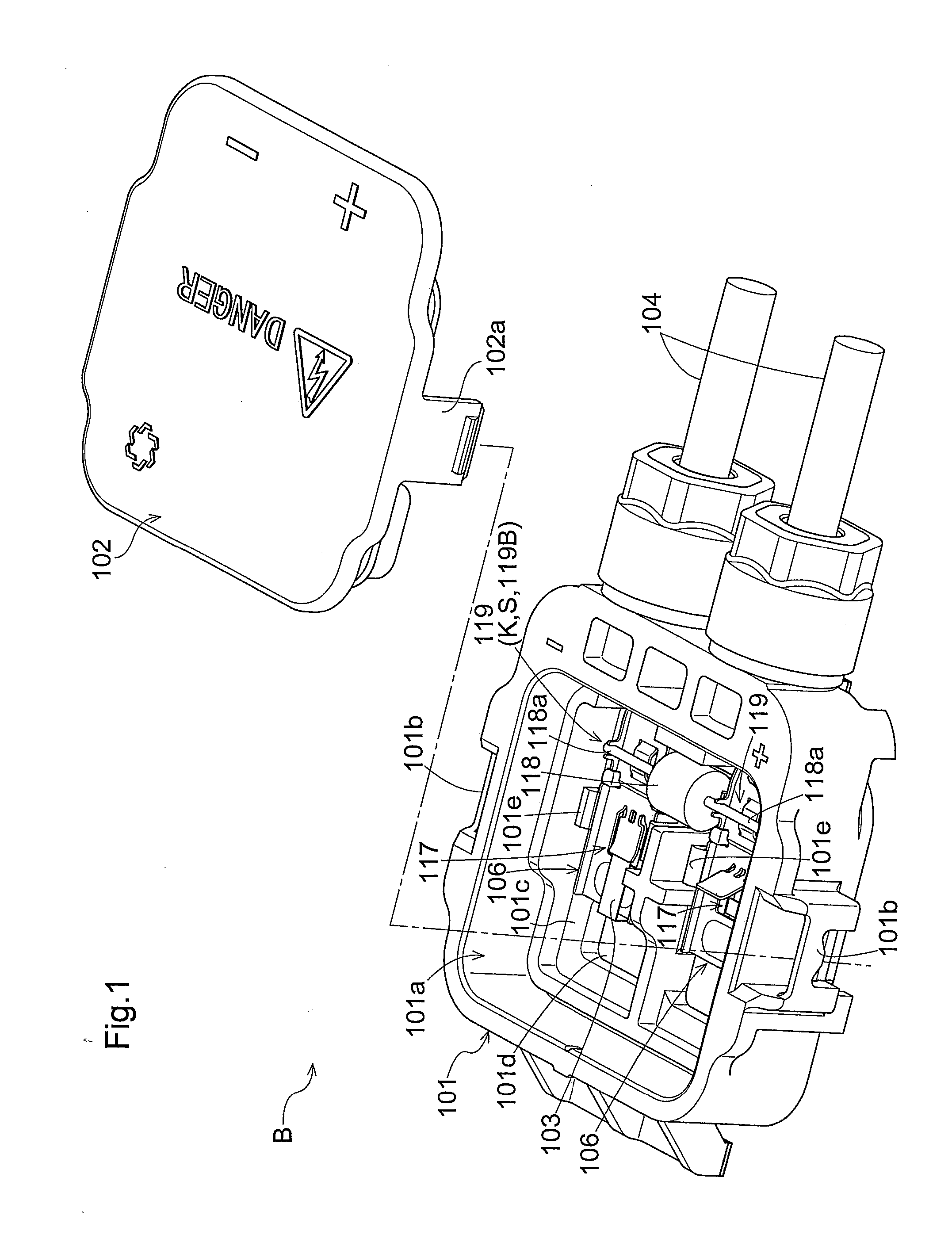
[0064]Hereinbelow, embodiments of the present invention will be described with reference to the drawings. FIG. 1 shows a terminal box B for a solar cell module according to the present invention. The terminal box B includes: a main body 101 made of resin; and a lid 102 made of resin for closing an opening 101a of the main body 101.

[0065]The main body 101 has a pair of locking parts 101b integrally formed on respective lateral sides of the main body 101. The lid 102 has a pair of claws 102a integrally formed on respective lateral sides of the lid 102. By pushing the claws 102a of the lid 102 into the respective locking parts 101b of the main body 101 and allowing the claws 102a and the respective locking parts 101b to lock together, the opening 101a of the main body 101 is closed with the lid 102.

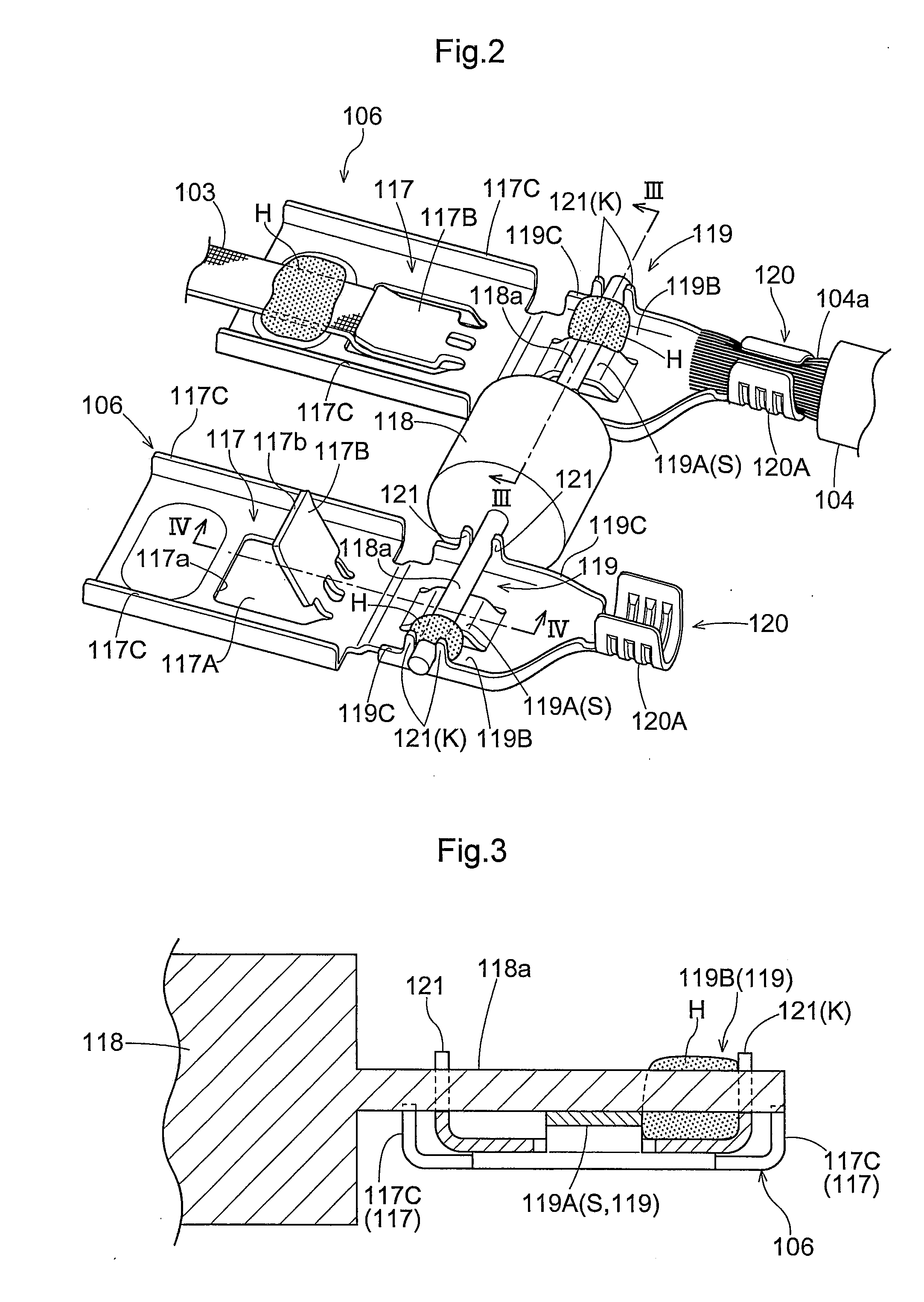
[0066]Inside the main body 101, a pair of terminal strips 106 are attached. A pair of the terminal strips 106 are configured to electrically connect a pair of respective band plate-shaped ou...

embodiment 2

[0079]FIG. 5 shows a terminal box B for a solar cell module according to the present invention. The terminal box B includes: a main body 201 made of resin; and a lid 202 made of resin for closing an opening 201a of the main body 201.

[0080]The terminal box B is in a shape of a flat cuboid. The main body 201 has the opening 201a, and the opening 201a is closable by covering a front face part B1 with the lid 202. A rear face B2 of the main body 201 is formed as an adhesive surface 207 to which an adhesive material for attaching to a solar cell module M is applicable. From among four lateral faces of the terminal box B (the main body 201), one lateral face (first lateral face) B3 is provided with a pair of connection parts 208 for connecting a pair of respective external cables 204. In addition, the other lateral face (second lateral face) B4 which is on an opposite side to the lateral face B3 is provided with a reinforcing rib 209 which juts out and comes into contact with a surface of...

embodiment 3

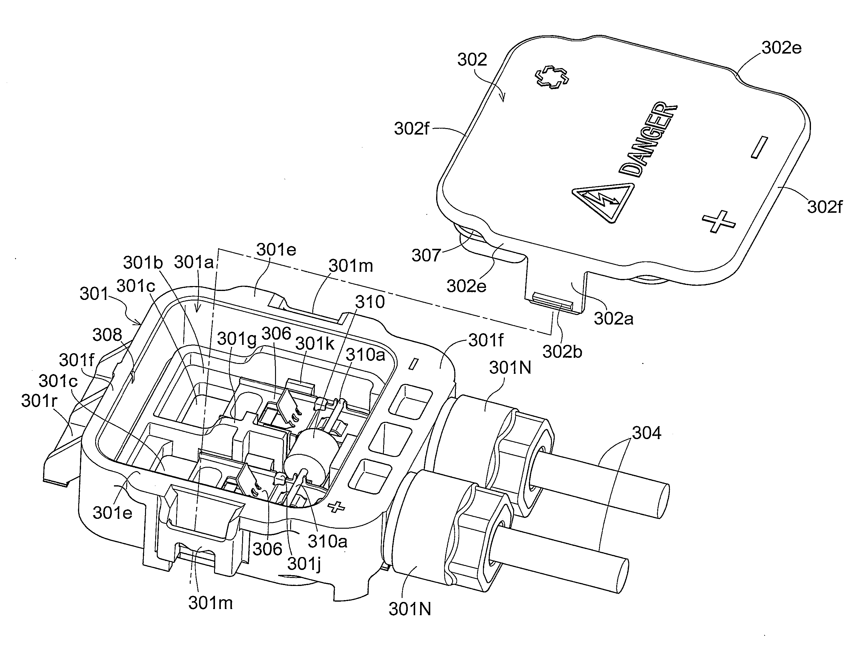
[0096]FIG. 10 shows a terminal box for a solar cell module according to the present invention. The terminal box includes: a main body 301 made of resin; and a lid 302 made of resin for closing an opening 301a of the main body 301. The lid 302 can close the opening 301a through connection holding to the main body 301 achieved by a retention mechanism.

[0097]As shown in FIGS. 10-14, a pair of terminal strips 306 are provided inside the main body 301 of the terminal box. A pair of the terminal strips 306 and respective lead wires 310a of a bypass diode 310 are connected by soldering with respective solders S. A pair of band plate-shaped output cables 303 (one example of output terminal) of the solar cell module are led through respective introduction ports 301c of a bottom wall 301b of the main body 301 into the main body 301, and the output cables 303 and the respective terminal strips 306 are connected by soldering with the respective solders S. In addition, a pair of power cables 304...


PUM


Abstract

A terminal box includes: a main body (101); at least one pair of terminal strips (106) which are connectable to a positive electrode and a negative electrode of a solar cell module; and a backflow prevention diode (118) bridged between the terminal strips (106) to connect the terminal strips (106). The terminal strip (106) and the backflow prevention diode (118) are contained in the main body (101). The terminal strip (106) includes: a supporting part (S) for supporting a lead wire (118a) of the backflow prevention diode (118) in a mounted state; a pinching part (K) for supporting the lead wire (118a) in a pinched state; and a recess (119B) which is provided between the supporting part (S) and the pinching part (K) and configured to position a connecting solder upon connecting the lead wire (118a) and the terminal strip (106).

Description

BACKGROUND[0001]1. Field of the Invention[0002]The present invention relates to a terminal box used for a solar cell module.[0003]2. Description of the Related Art[0004]A conventional terminal box includes a main body containing: at least one pair of terminal strips which are connectable to a positive electrode and a negative electrode of a solar cell module; and a backflow prevention diode bridged between the terminal strips to connect the terminal strips. In this type of the terminal box, a pair of the planar terminal strips are arranged in parallel at a distance, the backflow prevention diode is bridged between the terminal strips in such a manner that a lead wire of the backflow prevention diode is placed across a full width of the corresponding terminal strip, and the lead wire is soldered (see, for example, Japanese Utility Model Registration No. 3069523).[0005]In the conventional terminal box described above, the lead wire of the backflow prevention diode is soldered while th...

Claims


Application Information

Patent Timeline
IPC IPC(8): H05K7/20H02G3/18
CPCH02S40/34H02G3/08H02S40/00Y02E10/50
Inventor MASUMOTO, YUTAKA
Owner HOSIDEN CORP
Why Eureka
Try Eureka