Refrigerant cycle with operating range extension

a refrigerant cycle and operating range technology, which is applied in the direction of machines/engines, positive displacement liquid engines, lighting and heating apparatus, etc., can solve the problems of slowing the speed of the motor operation and the refrigerant cycle, and achieve the effect of reducing the capacity, reducing the load and thus the load

Inactive Publication Date: 2005-08-09
CARRIER CORP
View PDF15 Cites 124 Cited by
  • Summary
  • Abstract
  • Description
  • Claims
  • Application Information

AI Technical Summary

Benefits of technology

[0008]Further, if the electric motor for driving a compressor is a multi-speed or variable speed motor, a motor control may slow the speed of operation of the motor to also reduce the load. Notably, for purposes of the claims in this application, the term “variable speed motor” should be understood to mean either a multi-speed motor having several discrete speeds, or an infinitely variable speed motor. That is, either type motor would be useful for this invention, and will be referred to generically as a “variable speed” motor. Additionally, other known methods such as cylinder unloading, slide valves, suction port restriction, etc. can be utilized for the same purpose for various types of compressors. All of these control steps could result in the refrigerant cycle being at a capacity that is less than what may be in demand or desirable for the particular environmental conditions. However, by reducing the capacity, and thus the load, the compressor may avoid a shutdown that would otherwise occur. As such, overall, a more desirable result occurs, even though the refrigerant cycle may be operating at a less than otherwise desired capacity.

Problems solved by technology

Further, if the electric motor for driving a compressor is a multi-speed or variable speed motor, a motor control may slow the speed of operation of the motor to also reduce the load.
All of these control steps could result in the refrigerant cycle being at a capacity that is less than what may be in demand or desirable for the particular environmental conditions.

Method used


Image

  • Refrigerant cycle with operating range extension
  • Refrigerant cycle with operating range extension

Examples


Embodiment Construction

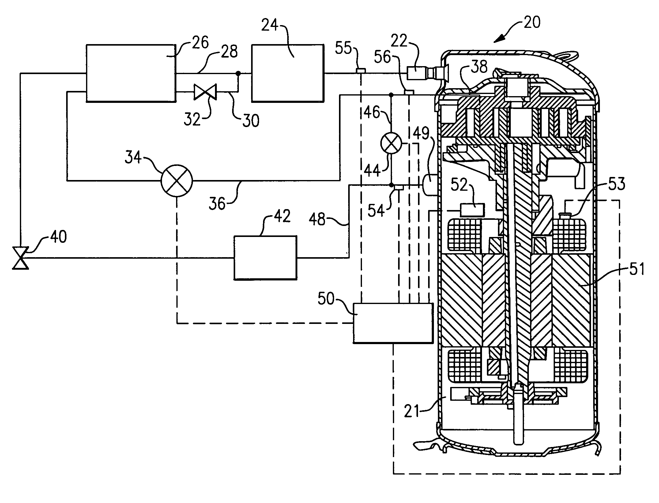
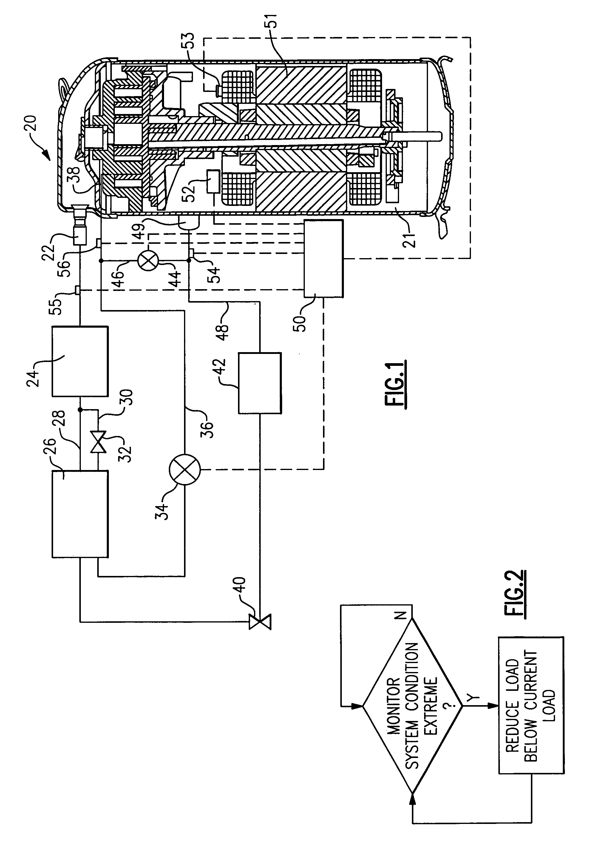
[0013]FIG. 1 shows a refrigerant cycle 20 having a compressor 21 delivering a refrigerant to an outlet port 22. From outlet port 22, the refrigerant travels to a condenser 24. As known, in condenser 24, the refrigerant exchanges heat with a source of outside air.

[0014]Downstream of condenser 24 is an economizer heat exchanger 26. A main refrigerant flow line 28 delivers refrigerant from the condenser 24 to a first branch of the economizer heat exchanger 26. A line 30 taps a portion of the refrigerant from the main refrigerant line 28 and passes this tapped refrigerant through an economizer expansion device 32. Now, the refrigerant in the tapped line 30 is cooler than the refrigerant remaining in the line 28. In the economizer heat exchanger 26, the tapped refrigerant subcools the main refrigerant in line 28. The tapped refrigerant is returned through a shut-off valve 34 in line 36, to an intermediate compression point 38 in the compressor 21.

[0015]As shown, the compressor 21 is a sc...


PUM


Abstract

A refrigerant cycle is provided with a control that monitors system conditions such as current, voltage or temperature at a compressor motor or refrigerant state conditions at compressor ports. A protection switch on the motor is operable to stop operation of the compressor should a system condition exceed a predetermined maximum. The control monitors a system condition, and determines that the system condition indicates the protection switch may be actuated as the condition is moving toward the predetermined limit. Under such conditions, the control moves the compressor to a less loaded mode of operation such that it is less likely that the protection switch will actuate.

Description

BACKGROUND OF THE INVENTION[0001]This invention relates to a concept that monitors system conditions in a refrigerant cycle, and reduces the compressor load should those conditions approach an extreme condition, in order to prevent system nuisance shutdowns and complete loss of cooling load by end users.[0002]Refrigerant cycles are utilized for HVAC systems, refrigeration units, and various other applications. In conventional refrigerant cycles, a compressor compresses a refrigerant and delivers that refrigerant to a condenser. From the condenser, the refrigerant travels to an expansion device, and from the expansion device, to an evaporator. From the evaporator, the refrigerant is returned to the compressor.[0003]One recent development in the refrigerant cycle art is the inclusion of an economizer cycle. In an economizer cycle, a portion of the refrigerant downstream of the condenser is tapped off and passed through an economizer expansion device, and then into an economizer heat e...

Claims


Application Information

Patent Timeline
Patent Type & Authority Patents(United States)
IPC IPC(8): F25B49/00F25B1/04F25B49/02
CPCF25B49/005F25B1/04F25B49/022F25B2400/13F25B2500/08F25B2600/0253F25B2600/0261F25B2600/2509F25B2700/15F25B2700/1931F25B2700/1933F25B2700/2106F25B2700/21151Y02B30/741Y02B30/70F25B49/00F25B49/02
Inventor LIFSON, ALEXANDERTARAS, MICHAEL F.
Owner CARRIER CORP
Why Eureka
Try Eureka