Earring support device

a technology of earring support and earring piercing, which is applied in the direction of bracelets, ear rings, wristwatch straps, etc., can solve the problems of wearers' discomfort, loss of earring ornaments, difficulty in affixing, etc., and achieves the effect of convenient inserting through earlobe piercing, minimizing discomfort for wearers, and being easily held in pla

Inactive Publication Date: 2005-08-09
CARMACK JACQUELINE M
View PDF22 Cites 20 Cited by
  • Summary
  • Abstract
  • Description
  • Claims
  • Application Information

AI Technical Summary

Benefits of technology

[0009]The present invention is directed to an earring support device or finding which is of one piece construction, is easily insertable through an earlobe piercing, is held easily in place, and which minimizes discomfort to the wearer.
[0010]The present invention departs from the prior art in its unitary construction, by using straight resiliently rigid lines and curves only when making transitions between sections. Curved (curvilinear) corners allow for ease when traveling through a piercing, yet the straight portions, when in place, maximize retention within the piercing.
[0011]The present invention is formed from one piece of resiliently pliable wire material. It is bent to provide a straight central portion, which ultimately rests in a straight piercing within the earlobe. At each end of the central portion, the wire is curvilinearly bent, so that two generally straight end members are provided. These extend outward, together, from the respective ends, with bends where they are attached so as to provide a generally curved and smooth transition from the central portion to the two end portions. The central portion and both end portions are in the same general plane, so that the device would lie substantially flat if laid upon a singularly planar surface. The end portions extend outwardly and generally toward each other. One end portion is formed into a loop at its outer end to provide a means for hanging an ornament. The other end portion is curved at its outer end, generally out and away from the other end portion. It is this end portion which is inserted through the ear piercing, with the curved portions of the device, in conjunction with the pliable nature of the earlobe, facilitating smooth passage. The central straight portion with curvilinear transition to the corresponding end portions, rests uniformly within the piercing through the width of the earlobe.

Problems solved by technology

There is not, however, full satisfaction with any of the existing prior art.
Wearers complain of the loss of earring ornaments, discomfort, difficulty in affixing, or a combination thereof, with regard to existing earring findings.
A number of existing applications require two parts to make them secure, which presents difficulties in assembly and in fixation on the ear, because of the relatively small size of the individual parts.
Prior art using hinged mechanisms is also costly to produce.
Standard “shepherd hook” findings, which are essentially findings with a large, curved hook which fits through the lobe piercing, without a separate fastener, are relatively easy to use and easy to attach an ornament to, but are also easily disengaged and often lost, along with the suspended ornament.

Method used


Image

  • Earring support device
  • Earring support device

Examples


Embodiment Construction

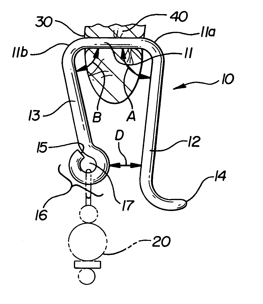
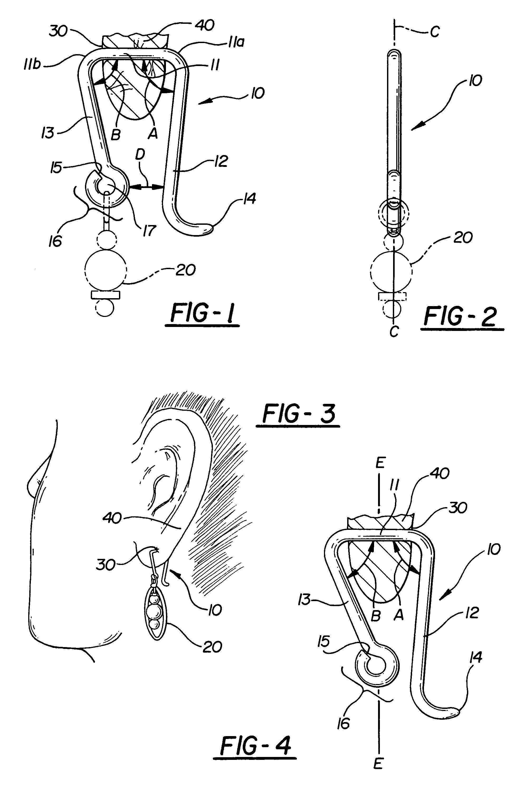
[0017]The invention, earring support device, broadly considered, comprises a formed, rigidly resilient, single filament member 10, which, in the preferred embodiment, the rigidly resilient, single filament is a fine gauge wire. Rigidly resilient is defined as being substantially non-bendable, thus, if moved to a degree, is not rigidly breakable and will return to its position. Member 10 further has a straight center portion or section 11, with a first end 11a and a second end 11b. A first end section 12 extends in a curvilinear relationship from section 11 at first end 11a at angle A. Angle A is no greater than 90° and in the preferred embodiment angle A is less than 90°.

[0018]A second end section 13 extends in curvilinear relationship at angle B from section 11 at second end 11b. Angle B is no greater than 90° and in the preferred embodiment angle B is less than 90°.

[0019]First end section 12 terminates at first outer end 14. Second end section 13 terminates at second outer end 15....


PUM


Abstract

An earring support device, or finding, which is inserted through a substantially horizontal piercing in the user's earlobe and from which an earring ornament is suspended. A horizontal straight center section of the support is provided to correspond with the piercing of the earlobe and minimize discomfort from the weight of the ornament. The device has two downward portions curvedly attached to, and, suspended, from each end of the horizontal section. One downward portion has a loop at its end to suspend an ornament. The other downward portion is inclined inwardly to hold the support in place.

Description

BACKGROUND OF INVENTION[0001]The concept of utilizing a hook, or “finding”, to insert through a piercing in a wearer's ear is obviously known. U.S. Pat. No. 1,419,021, to Cicerchi discloses an earring assembly, a portion of which is inserted through a piercing in the wearer's lobe. Similarly, U.S. Pat. No. 5,044,176, to King, is directed to a support cradle for a pierced earring, to reduce stress to the user's earlobe. U.S. Pat. No. 371,283, to Smitten, discloses an earring assembly for a pierced ear with a locking mechanism to hold the earring in place. U.S. Pat. No. 360,423, to Edge, discloses a pierced earring with a spring bow and catch. Another example of prior art is U.S. Pat. No. 4,249,393, to Ciambra, for an earring which loops the bottom portion of the wearer's lobe and penetrates a piercing. U.S. Pat. No. 208,230, to Fuller, demonstrates that use of a finding to hold an earring in place was known in 1878.[0002]Including those mentioned in the referenced prior art, these ar...

Claims


Application Information

Patent Timeline
Patent Type & Authority Patents(United States)
IPC IPC(8): A44C5/00A44C7/00
CPCA44C7/00
Inventor CARMACK, JACQUELINE M.
Owner CARMACK JACQUELINE M
Why Eureka
Try Eureka