
Contact lens for correcting myopia and/or astigmatism

a contact lens and astigmatism technology, applied in the field of myopia and/or astigmatism correction contact lenses, can solve the problems of presenting an inherent risk of permanent damage to a patient's eye, many patients are unwilling to undergo these surgical procedures to correct the curvature of the cornea, and the effect of improving the desired shape and functional vision

Inactive Publication Date: 2005-08-09
MITSUI IWANE
View PDF8 Cites 6 Cited by
  • Summary
  • Abstract
  • Description
  • Claims
  • Application Information

AI Technical Summary

Benefits of technology

[0047]As with the optical contact lens of the aforementioned U.S. Patent, in a myopia and / or astigmatism-correcting contact lens of the present invention, application of this contact lens to a patient's cornea results in reshaping of the cornea and provides improved visual acuity. In a preferred embodiment, once a patient's cornea has achieved an optimal shape, as determined by functional visual acuity, the contact lens of the present invention may be temporarily removed without loss of visual correction. However, a patient may maintain the desired shape of the cornea by wearing the optical contact lens for a short period of time, e.g., approximately three to eight hours per day. For example, in some instances, a patient may wear the contact lens one or two nights a week or every night during sleep to maintain the desired shape and functional vision.

Problems solved by technology

While these surgical procedures effect long lasting correction of visual defects, they present an inherent risk of permanent damage to a patient's eye.
However slight this risk might be, many patients are unwilling to undergo these surgical procedures to correct the curvature of the cornea.
However, it was significantly effective only for European and American but less effective for Asian.

Method used


Image

  • Contact lens for correcting myopia and/or astigmatism
  • Contact lens for correcting myopia and/or astigmatism
  • Contact lens for correcting myopia and/or astigmatism

Examples


first embodiment

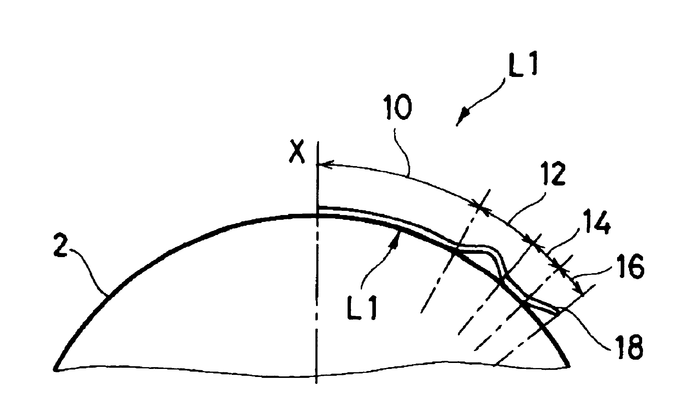
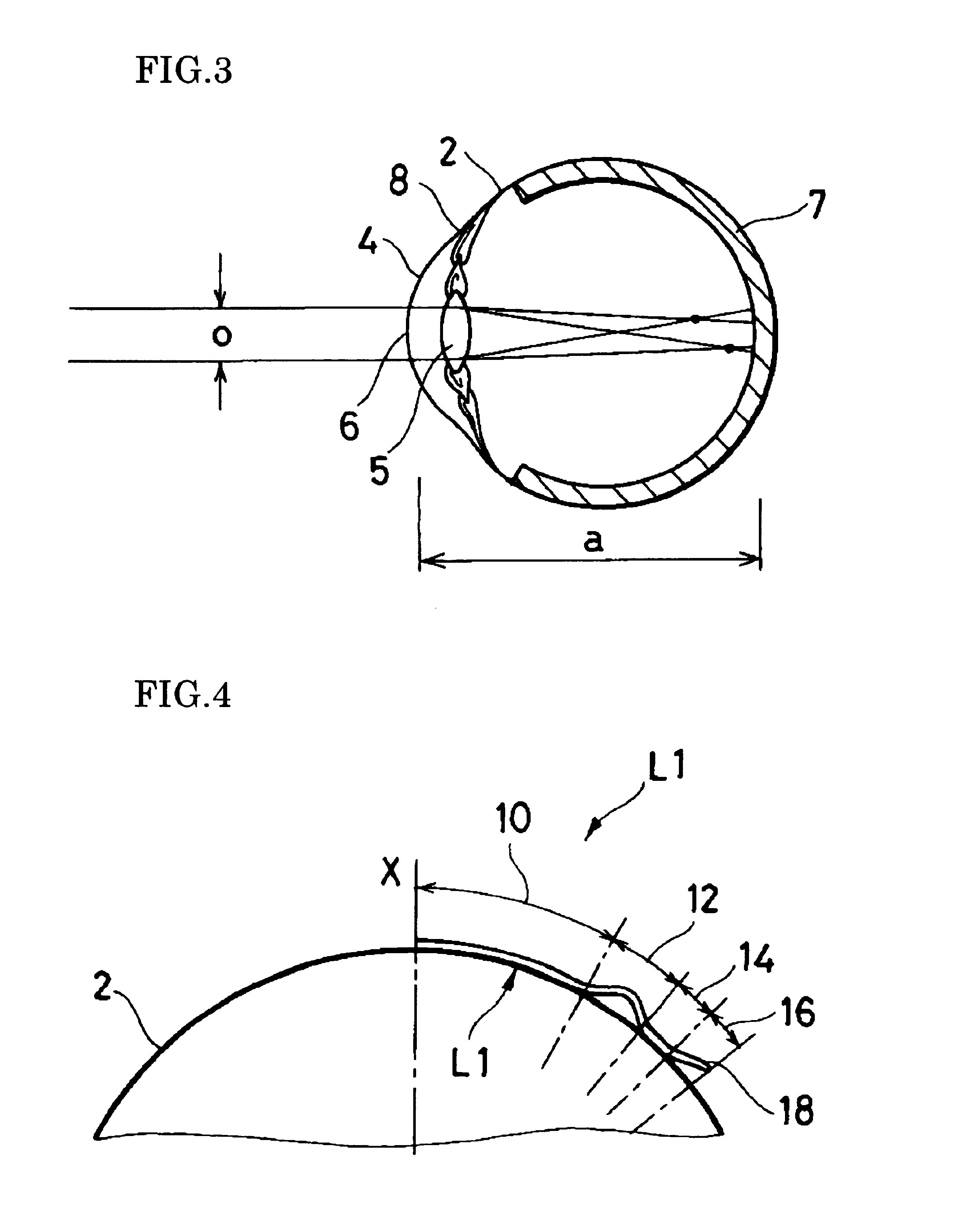
[0059]The contour and shape of the contact lens L1 are shown in FIG. 4 in an exaggerated form. The contour of the contact lens L1 is designed to treat myopia or astigmatism. In FIG. 4, the contact lens L1 is symmetrical with respect to the axis X.

[0060]The contact lens L1 includes at its center a pressure zone 10 which will overlay or engage a region of the corneal surface where alteration is desired. When the contact lens L1 is placed on the eye, the pressure zone 10 will apply a relative pressure to the underlying or engaged region of the cornea. It is understood that the contact lens L1 is separated from the cornea by fluid, e.g., tears present between the lens and the surface of the cornea but the fluid follows the contour of the cornea.

[0061]The contact lens L1 also includes an annular relief zone 12 positioned at the periphery of the pressure zone 10. The relief zone 12 is an area adjacent to the pressure zone 10 that creates a space or void between the surface of cornea and ...

second embodiment

[0089]A contact lens L2 comprises: a pressure zone 110 having a first surface defined by the inner surface of the contact lens located on the side of a patient's cornea and positioned at the center of the contact lens, wherein the first surface is formed in a concave shape having a curvature less than that of the central surface of the patient's cornea; a relief zone 112 having a second surface defined by the inner surface of the contact lens located on the side of the patient's cornea and positioned at the periphery of the pressure zone 111, wherein the second surface is formed in a concave shape; a first anchor zone 114a having a third surface defined by the inner surface of the contact lens on the side of the patient's cornea and positioned at the periphery of the relief zone 112, wherein the third surface is formed in a concave shape; and a second anchor zone 114b having a fourth surface defined by the inner surface of the contact lens on the side of the patient's cornea and po...

example 1

m With the Features of the Contact Lens L1 of the First Embodiment

[0098]A Japanese patient A initially wore a soft contact lens every day to correct myopia. The patient was diagnosed with myopia through the measurement of refractive error. According to the measurement of the topography of central curves of the right and left eyes, the diopter of the right eye was 38.50 (refractive error: −4.25, uncorrected vision: 0.1) and the diopter of the left eye was 39.00 (refractive error: −4.00, uncorrected vision: 0.1).

[0099]Based on the above measurements, BCs of the contact lenses of the patient's right and left eyes were arranged at 35.50 D and 36.00 D, respectively.

[0100]Then, according to the present invention, RC and AC were determined using the following two formulas.

RC=BC+8.0 D

AC=BC+3.0 D

[0101]As a result, RC and AC of the right eye's contact lens were 43.50 D and 38.50 D, respectively. Further, RC and AC of the left eye's contact lens were 44.0 D and 39.00 D, respectively.

[0102]Then...


PUM


Abstract

The present invention provides a myopia and / or astigmatism-correcting contact lens for correcting myopia and / or astigmatism based on the alteration in the shape of a patient's cornea. The myopia and / or astigmatism-correcting contact lens comprises a pressure zone having a first surface defined by the inner surface of the contact lens located on the side of the patient's cornea and positioned at the center of the contact lens. The first surface is formed in a concave shape having a curvature less than that of the central surface of the patient's cornea. The contact lens further includes a relief zone having a concave-shaped second surface defined by the inner surface of the contact lens located on the side of the patient's cornea and positioned at the periphery of the pressure zone, and an anchor zone having a concave-shaped third surface defined by the inner surface of the contact lens on the side of the patient's cornea and positioned at the periphery of the relief zone. The first surface has a curvature determined based on the shape of the patient's cornea to induce a specific desired alteration in the shape of the patient's cornea. Further, each of the curvatures of the first, second and third surfaces is arranged to satisfy the following formulas,RC=BC+7.0˜9.0 D (diopter), andAC=BC+2.0˜4.0 Dwhere BC is the curvature of the first surface, RC is the curvature of the second surface, and AC is the curvature of the third surface.

Description

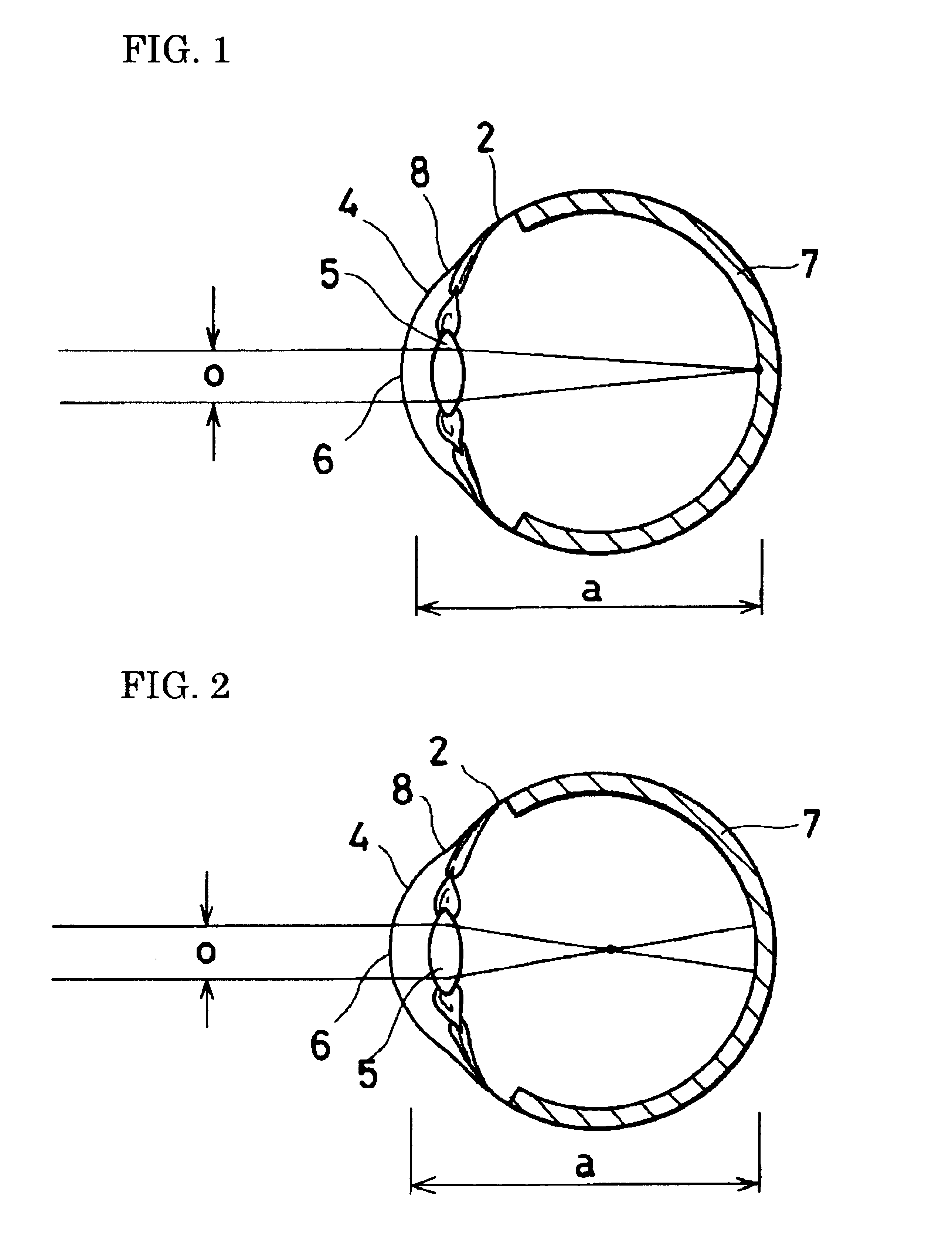
CROSS-REFERENCE TO RELATED APPLICATION[0001]This application is a continuation of U.S. patent application Ser. No. 10 / 073,081 filed Feb. 12, 2002 now abandoned.FIELD OF THE INVENTION[0002]The present invention relates to a contact lens for correcting myopia and / or astigmatism. More specifically, the present invention relates to a myopia and / or astigmatism-correcting contact lens for reshaping the cornea based upon corneal topography to effect correction of visual defects.BACKGROUND OF THE INVENTION[0003]Visual or optical defects which prevent parallel light rays entering the eye from focusing clearly on the retina exist in several varieties. In hyperopia (farsightedness), the point of focus lies behind the retina, generally because the axis of the eyeball is too short. In myopia (nearsightedness), the image is focused in front of the retina, generally because the axis of the eyeball is too long. In astigmatism, refraction is unequal on the different meridians of the eyeball, general...

Claims


Application Information

Patent Timeline
Patent Type & Authority Patents(United States)
IPC IPC(8): G02C7/04A61F9/00
CPCG02C7/047A61F9/0017G02C7/04
Inventor MITSUI, IWANE
Owner MITSUI IWANE
Learn More