Rear-view mirror with multiple interchangeable signals for vehicles with two, three, four or more wheels

a rear-view mirror and multiple interchangeable technology, applied in the field of new side mirrors, can solve the problems of limiting the visibility of the mirror, the concept of inapplicability, and the wide width of the panel separating the signal from the driver

Inactive Publication Date: 2005-08-09
RODRIGUEZ BARROS ALEJANDRO +1
View PDF22 Cites 91 Cited by
  • Summary
  • Abstract
  • Description
  • Claims
  • Application Information

AI Technical Summary

Problems solved by technology

These are very old and their concept is inapplicable, since the light signal is only visible to the rear and is dangerous as it shines in the drivers' eyes.
Also they are very bulky.
U.S. Pat. No. 2,457,348 P. A. Chambers 1946, discloses a signal projected to the side and to the rear, however the panel separating the signal from the driver is so wide that it is counterproductive and limits mirror visibility.
These consider non-interference with the driver's vision, but also present several inapplicable concepts since they are very bulky and do not consider any solutions for the inside of the mirror.
External screws are used and lighting surfaces that are impossible to approve.
The mirrors project considerably to the side and would break easily, as this is a critical area for scratches and knocks.
This is impossible to approve and is very bulky.
However, apart from producing turbulence, it is impossible to approve or manufacture on an industrial scale.
Since 1995, some new applications offering partial solutions have been filed, but they are expensive.
DE 296 07 691 U 1 Chen, Chun-Mng Taichung TW Apr. 27, 1996, proposes signals to the front and side, but does not resolve assembly or mirror interior, and it is therefore impossible to approve.
It is impossible to approve and comprises a fixed floor light of little use, because at a short distance the area it illuminates is very reduced, although it does comprise an optical diffuser.
It requires a very bulky housing that extends underneath and enlarges the lower edge.
If a fault occurs, the whole system has to be changed, which is very expensive.
It consists of a sealed unit with a tubular-shaped, standard lamp, but if a fault occurs, the complete subassembly must be changed, which is cumbersome.
Furthermore, the signal is dangerous as it always shines in the driver's eyes.
It does not resolve lighting source systems, or provide access for maintaining and assembling elements.
Its indirect, intermittent signal cannot be controlled, and, furthermore, it would be dangerous because when looking in the mirror, the signal would shine in the driver's eyes.
JP 62-191246(A) Kishosi Yamada, 1987, discloses a side light having one focus, but it increases the lower edge of the mirror considerably and does not determine the location of the motors that produce the relative movement of the various parts.
It is impractical, particularly with respect to temperature and aerodynamic noise.
Although, this system occupies little space, it wastes more than 70% of the original light input along the extensive surface.
To compensate, it uses several LEDs in a flat, traditional circuit, but does not manage to produce a strong enough light, and during the day when the outside light is more intense than inside light, the signal is only visible to the side and rear.
The system is very expensive and it has a sharp, protruding edge, which cannot be approved, since it is a dangerous design.
The system is based on an application of U Sho 60 161646 Suziki, and U.S. Pat. No. 5,402,103 Tashiro, and it is impossible to approve owing to the dangerous consequences when knocked, since the glass would shatter in this area.
It wastes a considerable amount of light energy and is expensive.
In use, it reduces the field of vision in the mirror and this does not comply with EEC Regulation No. 46 concerning car mirrors.
It is expensive, fragile and in order to operate, it requires an electronic circuit and 1500 V current transformer, which increases the system weight.
It is not a very reliable system since faults occur easily, and when they do, the whole system has to be changed.
These applications do not cover all the above-mentioned problem areas, or if they do, they do so only partially.

Method used


Image

  • Rear-view mirror with multiple interchangeable signals for vehicles with two, three, four or more wheels
  • Rear-view mirror with multiple interchangeable signals for vehicles with two, three, four or more wheels
  • Rear-view mirror with multiple interchangeable signals for vehicles with two, three, four or more wheels

Examples


embodiment

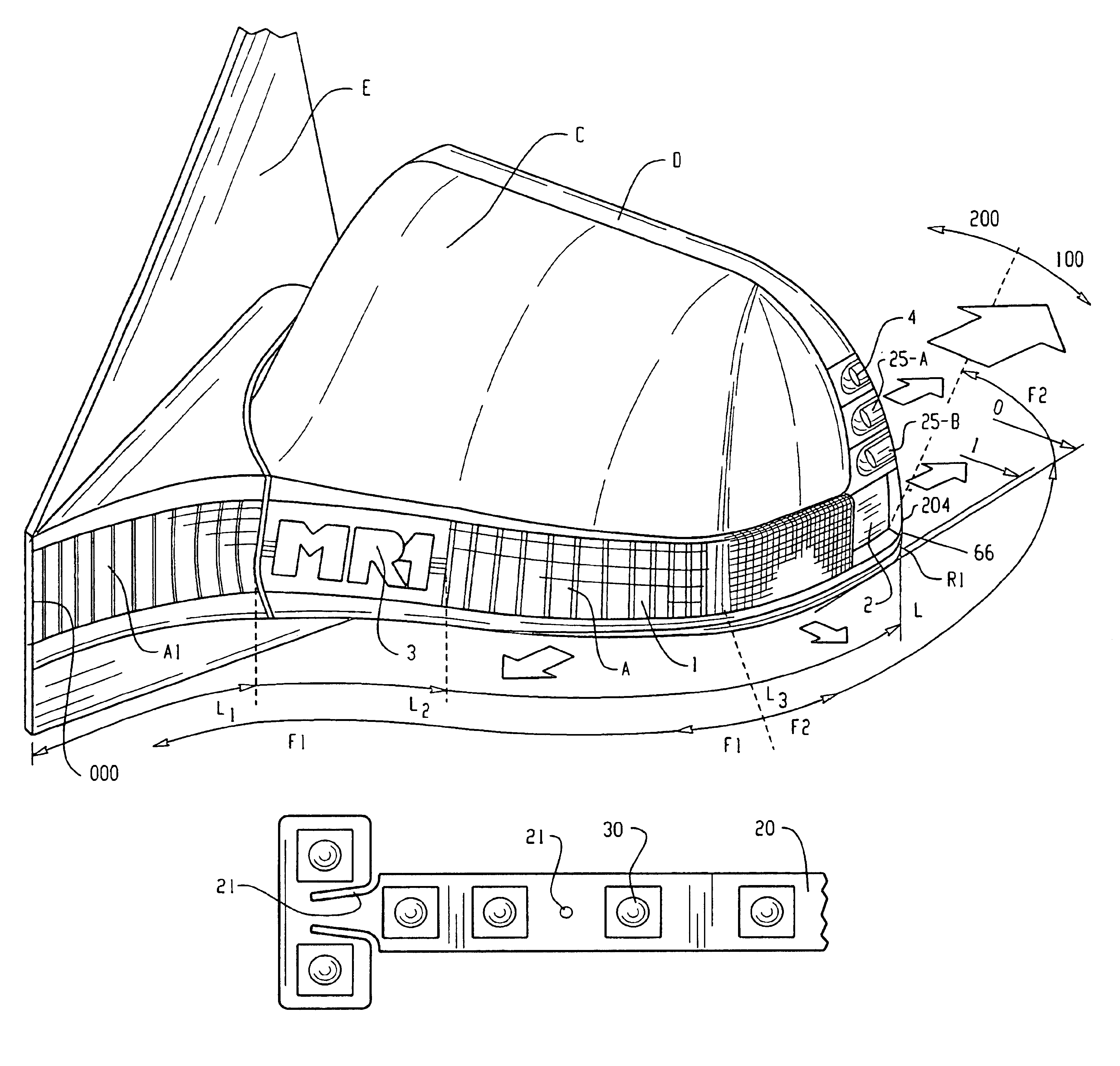
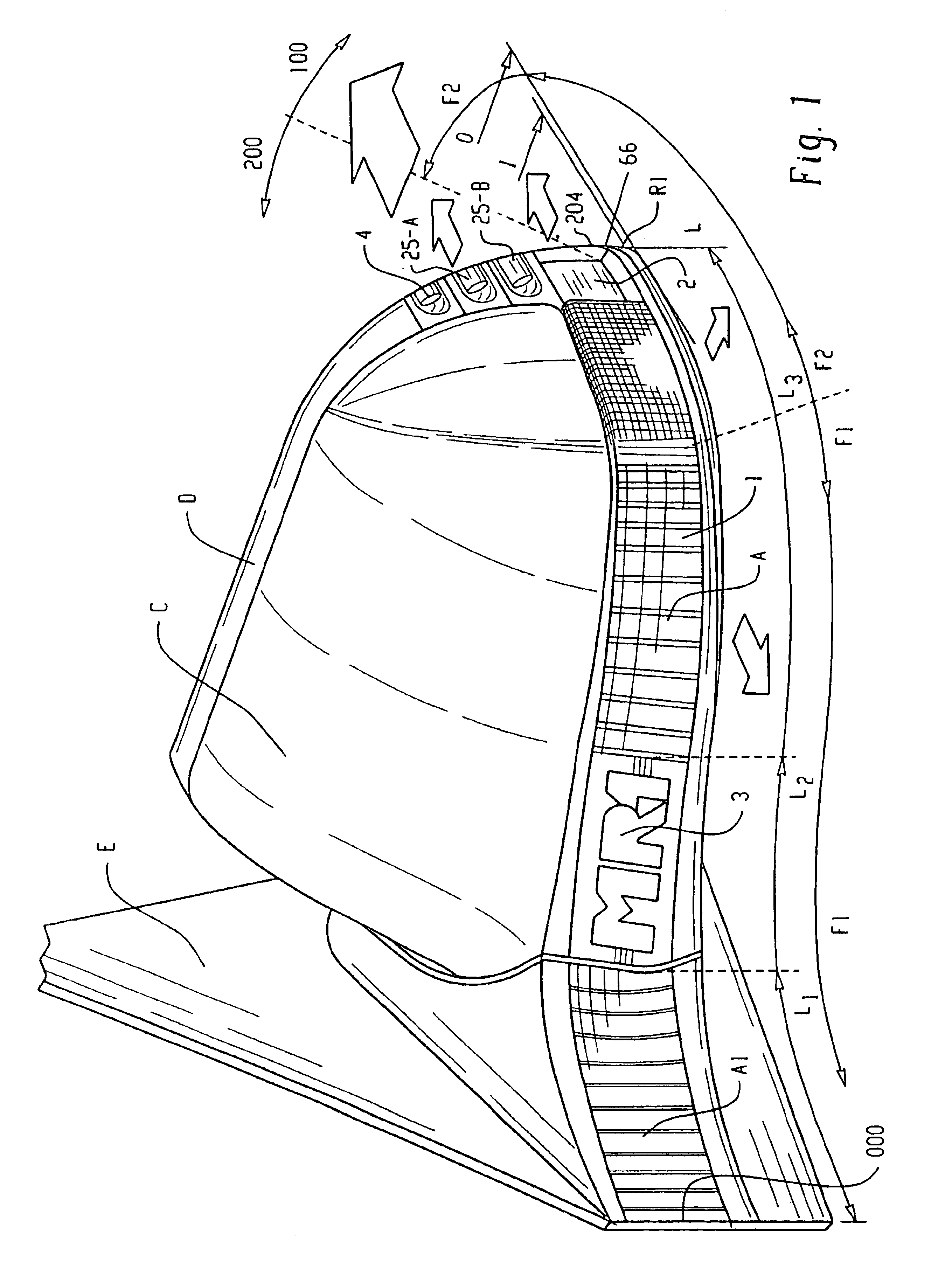
[0162]Its construction and assembly are simple. The mirror modules are interchangeable and can be combined, and the signals do not alter the outer appearance, whereas, the inside contains options for the source, light output, non-visible signals and sensors. There are three basic stages in the construction of the new modules (A), (B) and (A+B).

[0163]1. The structure composed of outer surfaces (1), internal housing (10) and the interconnections, fixing and shape features and access for changing parts (17), (39), (8), (9), (600), (P1), (DC), (50). See FIGS. 39, 40 and 42.

[0164]2. The composition of the circuit / source, components, flexible base, mixed circuit, LEDS, OLES, bulbs, sensors, photodiodes, LEDs, IR, operation circuits (20), (30), (32), (25), (310), (95). See FIGS. 32 to 38.

[0165]3. The optical variants, reflection elements, light conductors, and intermediate optics (6), (7), (12), (13), (150), (155).

[0166]Housing (D) or chassis-housing (D1), glass (50), support (E), cover (C...


PUM


Abstract

The invention relates to a rear-view mirror for vehicles, which consists of compatible, combinable and exchangeable modules such as: (A) and (B), or integrated (A+B), functional, signal, lighting and sensor modules; and structural (C), (D) and (E) modules; cover-housing, body-housing and support which may include functional modules. (A), (B) and (A+B) fulfill their function even if the rear-view mirror is folded. They use a multifocal light source of LED's inserted into a flexible and orientable circuit and / or a mixed rigid-flexible circuit combining LED's+bulbs and other lighting elements, with variable optical and reflective means enabling more than one signal from one same transparent surface with direct light output, indirect-reflected light output and / or through intermediate optical light guides depending on the directions required in the front, the side, the back and the lateral ground for different commands, applications and safety signals.

Description

CROSS-REFERENCE TO RELATED APPLICATIONS[0001]This application is a continuation of co-pending PCT Application No. PCT / ES01 / 00251 filed on Jun. 22, 2001, published in Spanish under PCT Article 21(2), which claims priority to Spanish Patent Application No. 200001834 filed Jul. 12, 2000.[0002]This invention relates to a new side mirror which normally uses direct and / or combined type optical systems, (mirrors, prisms, lenses and / or video camera). It is made up of signal producing and structural modules, of compatible shape and dimension, which cooperate with one another and can be interchanged, to combine subassemblies and form different models, using common parts for different vehicles having 2, 3, 4, or more wheels. Said modules are assembled in an anti-theft arrangement, since there is no visible access thereto from the outside. Said modules are made up of the following components:[0003]Module (A), which emits and receives multiple light and sound signals and other types, to and from...

Claims


Application Information

Patent Timeline
Patent Type & Authority Patents(United States)
IPC IPC(8): B60R1/12B60Q1/26G06M7/00
CPCB60Q1/2665B60R1/1207B60R2001/1215B60R2001/1223B60R2001/123B60R2001/1253Y10S362/80
Inventor RODRIGUEZ BARROS, ALEJANDRORODRIGUEZ FERNANDEZ, JOSE MANUEL
Owner RODRIGUEZ BARROS ALEJANDRO
Why Eureka
Try Eureka