Detention pond water quality apparatus and system

a technology for ponds and water quality, applied in water cleaning, multi-stage water/sewage treatment, sewage draining, etc., can solve the problems of clogging the water quality orifice of the outlet control structure, risky filtration system types, etc., to increase the available amount of surface area, not clogging the control structure, easy to be removed

Inactive Publication Date: 2005-08-09
WEIDMANN LAWRENCE W
View PDF24 Cites 14 Cited by
  • Summary
  • Abstract
  • Description
  • Claims
  • Application Information

AI Technical Summary

Benefits of technology

[0037]One advantage of the invention is that it allows water to drain from the pond in virtually the same amount of time as by specification of the pond because debris typically does not clog the inlet of the control structure.
[0038]Another advantage of the invention is that a plurality of inlet pipes of the invention increase the available amount of surface area for filtered drainage.
[0039]Another advantage of the invention is that debris that gathers on the invention can easily be removed by hand, and further does not clog the control structure.
[0040]Another advantage of the invention is that it includes a pipe cap that can be removed to provide orifices of varying size that provide different flow rates through the invention.
[0041]Another advantage of the invention is that all aspects can be observed and maintenance can easily be identified.

Problems solved by technology

This type of filtration system risks becoming clogged and water is unable to penetrate the elongated perforated pipe and thus cannot enter the outlet structure for release.
An additional failed method was to drill the correct size water quality orifice directly into the outlet structure and place a ½ round perforated pipe surrounded by gravel in front of it.
Therefore, larger debris such as large sediment, branches, leaves, garbage, can clog the water quality orifice of the outlet control structure, requiring maintenance after every rain event.

Method used


Image

  • Detention pond water quality apparatus and system
  • Detention pond water quality apparatus and system
  • Detention pond water quality apparatus and system

Examples


Embodiment Construction

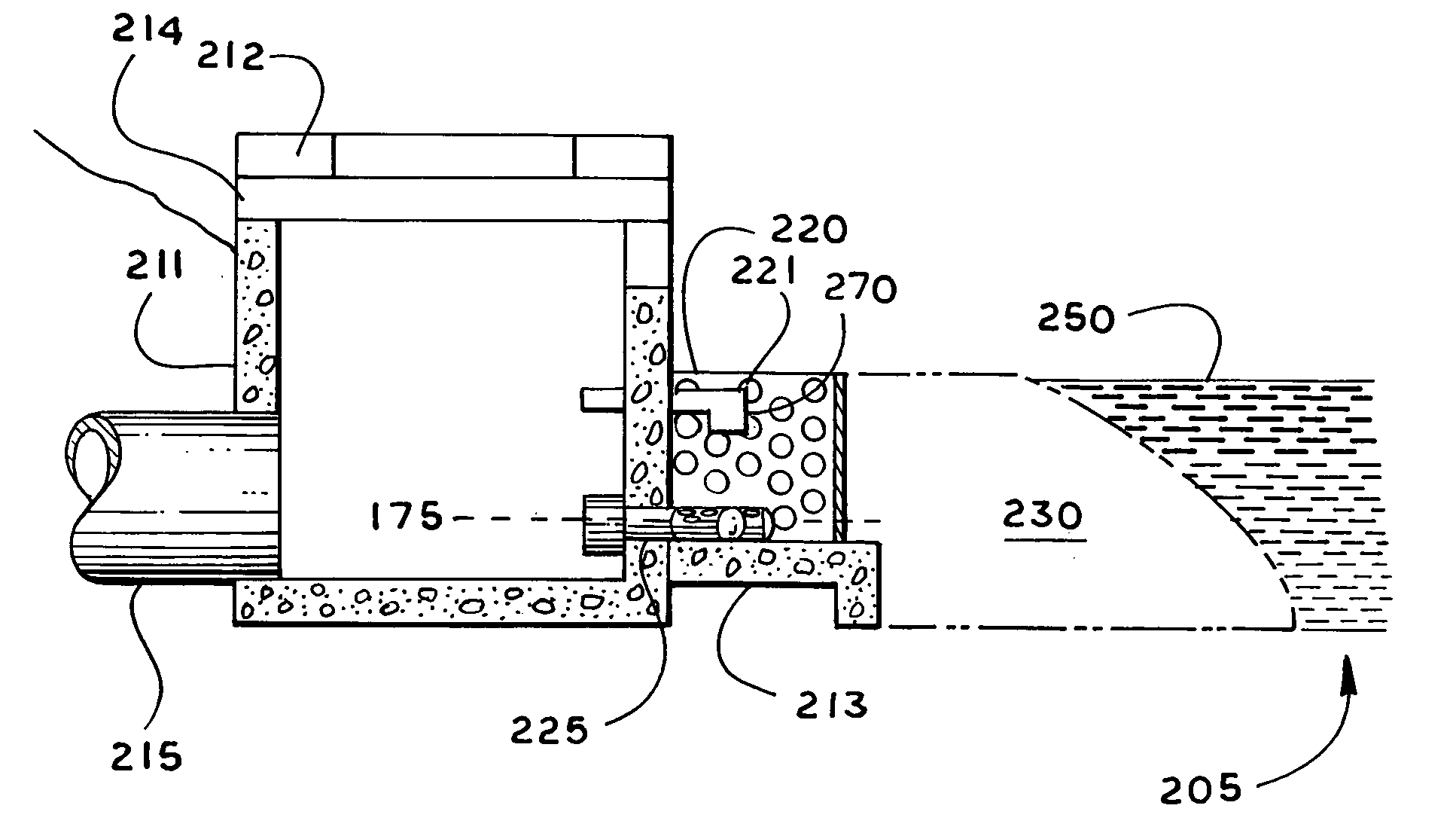
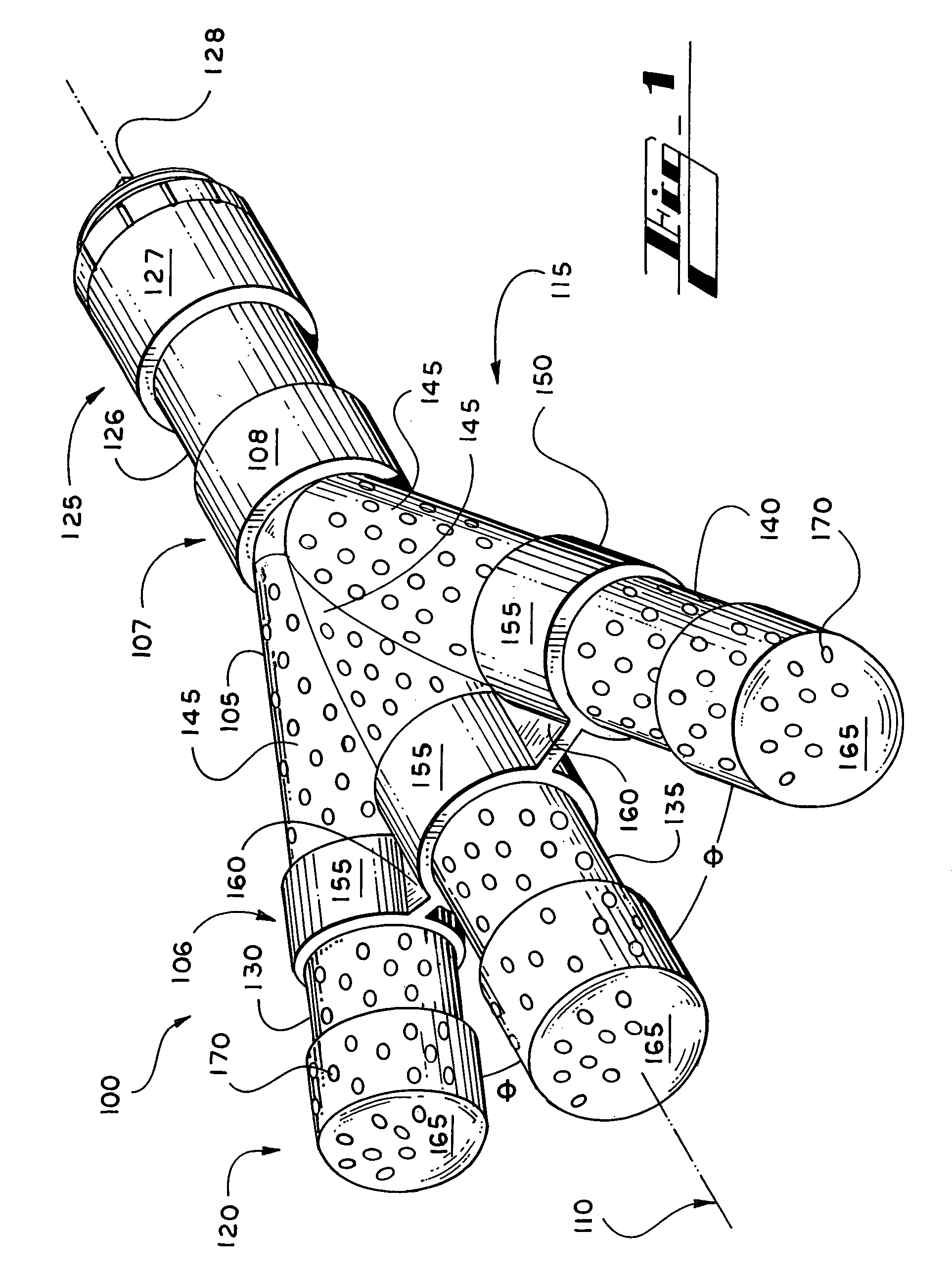
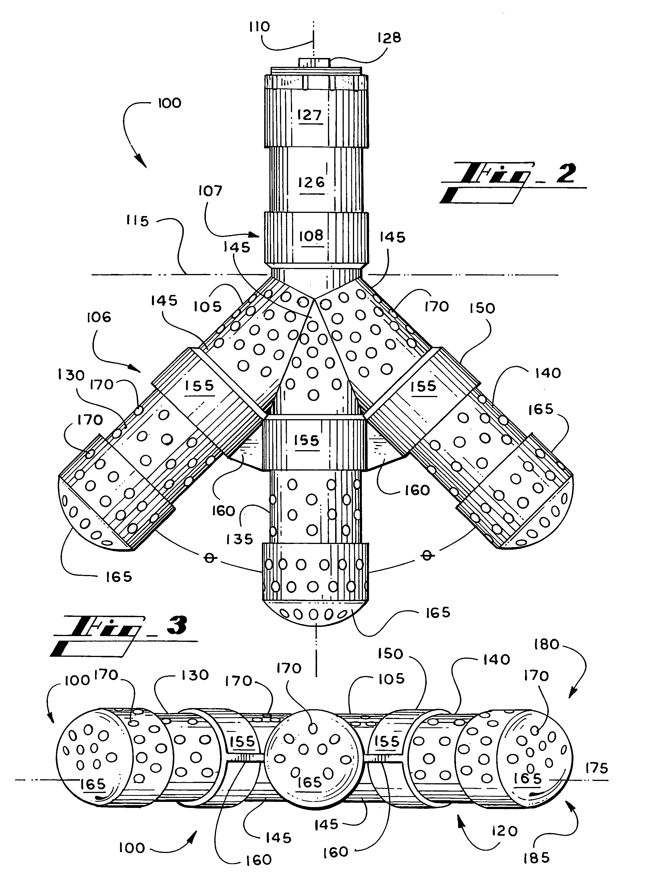
[0054]Referring to the drawings wherein like reference numerals designate corresponding parts throughout the several figures, reference is made first to FIG. 1 that illustrates a perspective view of an embodiment of a detention basin water quality apparatus 100. The apparatus 100 generally includes a central body 105 oriented about a longitudinal axis 110. The central body 105 generally includes a forward end 106 and a rear end 107.

[0055]The apparatus 100 can further be defined and cut by a plane 115 separating the main body 105 into an inlet portion 120 and an outlet portion 125. The outlet portion 125 generally includes the rear end 107 of the main body 105 as well as an outlet pipe 126. The outlet pipe 126 typically includes a ring 127 connected to the end of the outlet pipe 126. In a typical implementation, the ring includes inner threads that are in threaded engagement with a removable pipe cap 128.

[0056]The inlet portion 120 generally includes the forward end 106 of the main b...


PUM

PropertyMeasurementUnit
widthaaaaaaaaaa
frequencyaaaaaaaaaa
volumeaaaaaaaaaa

Abstract

A water quality apparatus and system utilized in permanent extended dry detention basins having an outlet control structure vertically mounted within a basin and a semi-round pipe (typically including gravel) attached to the forward edge. Typically, in this type of structure, debris flows over the top of the pipe and clogs the semi-round pipe and its outlet into the outlet control structure. The water quality apparatus is typically a pipe fixture having an outlet end that fits into the control structure and an inlet end comprising several perforated pipes (forming a series of holes) that protrude into the semi-round pipe. The holes allow the water to flow into the piping system and discourage any debris from flowing into the piping system and clogging it. As water flows through the gravel and into the perforated pipe, water can drain into the water quality apparatus and through the outlet control structure.

Description

BACKGROUND[0001]I. Field of the Invention[0002]The present invention relates generally to the field of water quality enhancement and more particularly to an apparatus and system for permanent extended-detention basins to treat storm water runoff through gravitational settling.[0003]II. Description of the Related Art[0004]Permanent extended-detention basins and other types of detention / retention basins are used in order to impound and temporarily store storm water runoff for a specified period and discharge it through a hydraulic outlet structure to a down stream conveyance system. An extended-detention basin is usually dry during non-rainfall periods. These basins are necessary and designed to provide for one, or all of the following: a) water quality enhancement, b) channel erosion control and, c) downstream flood control. These basins are installed when impervious surfaces are created from new development activities, which include subdivisions, commercial sites and other new devel...

Claims


Application Information

Patent Timeline
Patent Type & Authority Patents(United States)
IPC IPC(8): E03F1/00E02B11/00
CPCE02B11/00E03F1/002E03F5/0404C02F1/001C02F2103/001
Inventor WEIDMANN, LAWRENCE W.
Owner WEIDMANN LAWRENCE W
Why Eureka
Try Eureka