Molded parts with fabric surface areas and processes for their production

a technology of molded parts and fabric, applied in the directions of applications, transportation and packaging, other domestic articles, etc., can solve the problems of poor part appearance, inability to use a separate trim piece, and inability to mention any technique for securing and covering the fabric edges

Inactive Publication Date: 2005-08-09
DOW GLOBAL TECH LLC
View PDF38 Cites 51 Cited by
  • Summary
  • Abstract
  • Description
  • Claims
  • Application Information

AI Technical Summary

Benefits of technology

[0005]In one embodiment the present invention is a molded plastic article having a plastic substrate component with an adhered fabric surface piece where at least part of the fabric edges and fabric surface area adjacent the edges are overlapped by a molded-on, plastic edge-covering component. Preferably the molded-on, edge-covering component is an injection or compression molded plastic piece and more preferably it is selected from the group consisting of thermosetting polyurethane, thermosetting epoxy, thermosetting silicone, and the thermoplastics polycarbonate (“PC”), ABS, polypropylene (“PP”), high impact polystyrene (“HIPS”), polyethylene (“PE”), polyester, polyacetyl, thermoplastic elastomers, thermoplastic polyurethanes (“TPU”), nylon, ionomers, polyvinyl chloride (“PVC”) and blends of two or more of these thermoplastics. This invention is especially applicable to molded articles where the fabric is a synthetic leather or suede and/or the fabric has voids or openings and interior fabric edges. In an alternative embodiment the present invention is a process for preparing a molded plastic article of this type where an edge-covering component is molded onto and overlaps at least part of the fabric edges and fabric surface area adjacent the edges of a substrate component having an adhered fabric material. Preferably the edge-covering component which overlaps the edges of the fabric piece is molded on by injection or compression molding or by reaction injection molding in a second molding step. In

Problems solved by technology

However, none of these mention any technique for securing and covering the fabric edges.
It has been found, however, that this process results in poor part appearance because the fabric edge is not consistently covered by the injection molded plastic.
The attachment and use of a separate trim piece is not acceptable because it requires m

Method used


Image

  • Molded parts with fabric surface areas and processes for their production
  • Molded parts with fabric surface areas and processes for their production
  • Molded parts with fabric surface areas and processes for their production

Examples


examples

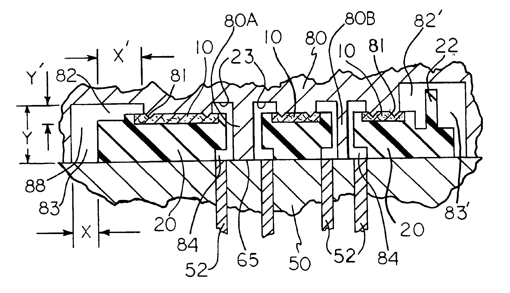
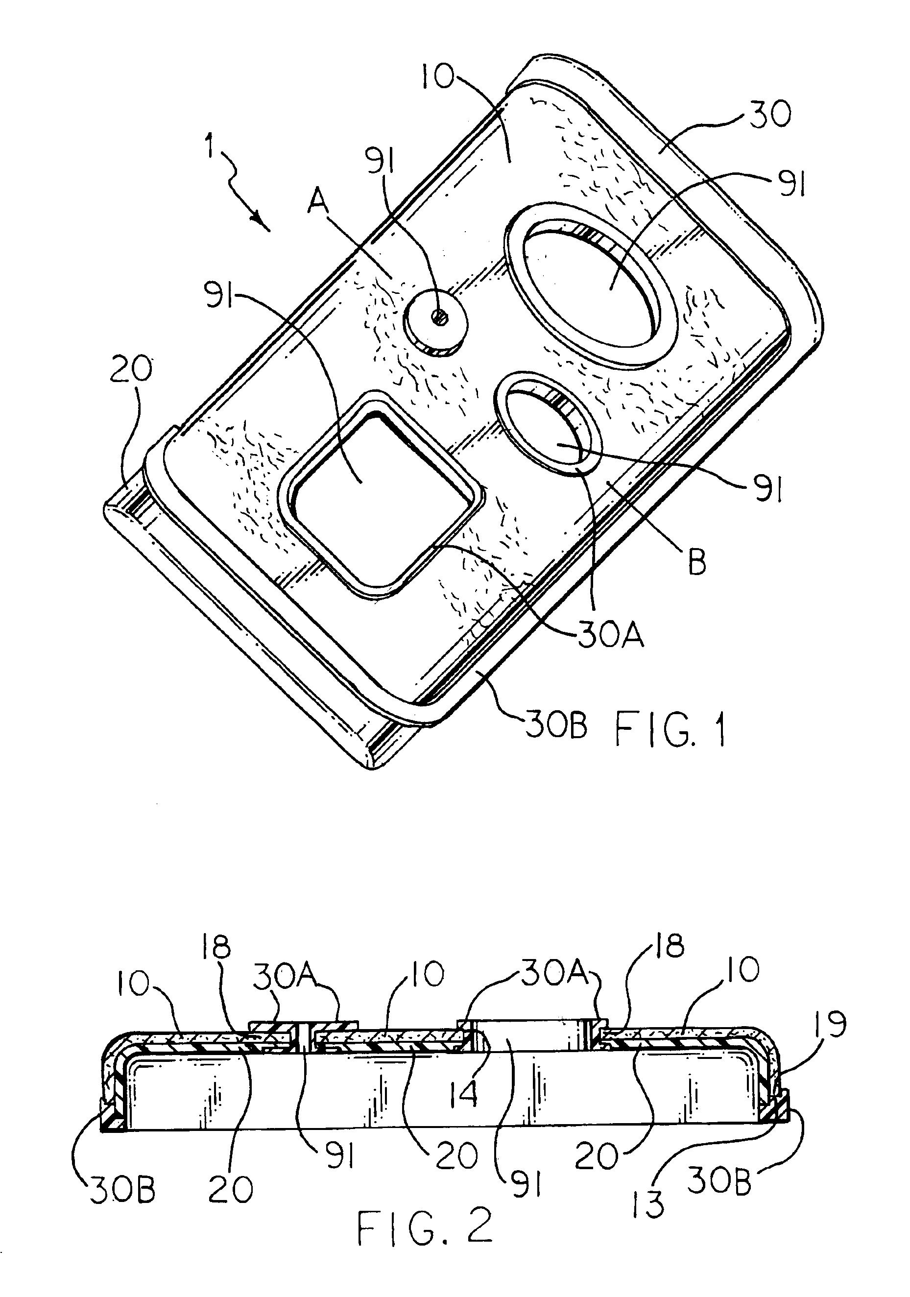
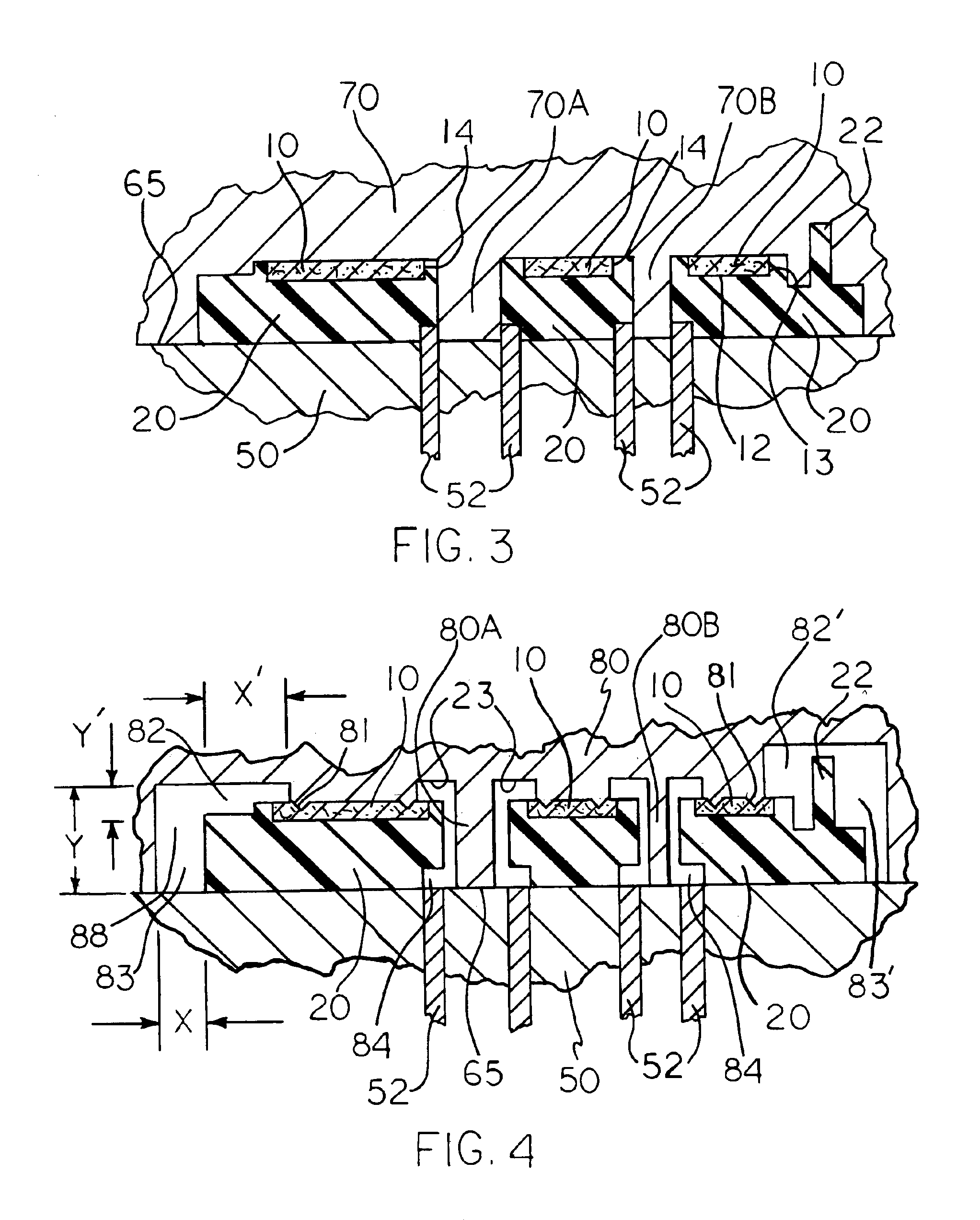
[0046]A part according to the present invention as shown in FIG. 1 was designed and produced generally as shown in FIGS. 1 through 6 and discussed above. The fabric is a non-woven polyester fabric which was laminated with a polycarbonate film 0.005 inches (approx. 0.015 mm) thick by the use of a thermally initiated adhesive, Dow adhesive film. The lamination was conducted at 220 degrees C. (set-point temperature for heating the rolls) on a two-roll laminator. The resulting laminate was pre-cut to the desired size and shape (including internal openings) such that the fabric does not reach the ends or edges of the empty mold cavity when it is inserted into the desired location between the cavity and the core on an injection mold. The desired fabric surface is placed against the cavity and held in place by the use of vacuum. The first injection molded material, a PC / ABS blend, is injected into the mold coming in contact with the PC film. The flow of the injection molded thermoplastic, ...


PUM

PropertyMeasurementUnit
Flow rateaaaaaaaaaa
Areaaaaaaaaaaa
Surface areaaaaaaaaaaa

Abstract

The present invention thus provides a fabric-laminated plastic part and a novel process where the fabric edges are covered with a second plastic component that adheres both to the fabric and to the first plastic material. A first plastic substrate component is prepared with an adhered fabric surface area and then the edges of the fabric are overlapped by a second molded-on, plastic edge-covering component. The second material covers the fabric edge to provide an aesthetically pleasing surface. This construction produces a more durable fabric edge covering and eliminates the tendency of the fabric to peel off the molded part during use.

Description

[0001]This invention relates to injection molded plastic parts having a fabric surface area and a process for making these parts where the fabric edges are secured in a very effective and aesthetically pleasing manner. Parts are produced with good appearance, precise dimensions, thin part cross section and stable, secure fabric edge coverings.BACKGROUND OF THE INVENTION[0002]There are a number of processes for providing a surface layer of a fabric, such as leather or simulated leather, onto all or part of the surface of molded plastic parts. Using an injection molding process and pre-inserting a fabric surface piece in front of or into the mold is discussed in JP 54-018,039; JP 57-029,436; DE 4,015,071; EP 1,157,799; and U.S. Pat. No. 4,849,145.[0003]In JP 54-018,039 a fabric is held in the mold and forced against the opposite side of the mold cavity by injected plastic. DE 4,015,071 and JP 57-029,436 teach the use of a film between the fabric and the injected, molten plastic. In EP...

Claims


Application Information

Patent Timeline
IPC IPC(8): B29C45/00B29C45/14B29C45/16B29C45/26B29C39/10B29K63/00B29K75/00
CPCB29C45/0046B29C45/1671B29C45/14344B29C45/14811B29C45/1676Y10T428/24322B29C2045/14909B29K2711/08B29K2713/00B29K2715/006Y10T428/24273B29C2045/14901Y10T428/2395B29C45/16B29C45/14B32B33/00
Inventor HUS, MICHAEL E.LANGMAID, JOSEPH A.PETERSON, CURT E.WENZEL, JEFFREY D.
Owner DOW GLOBAL TECH LLC
Why Eureka
Try Eureka