Liquid crystal display including at least two light guiding plates abutting each other

a technology of light guiding plate and liquid crystal display, which is applied in the direction of identification means, instruments, planar/plate-like light guides, etc., can solve the problems of increasing the size and thickness of the back light assembly increasing the size of the light guiding plate, and not increasing the thickness of the lcd panel to a large degree, etc., to achieve the effect of large screen siz

Inactive Publication Date: 2005-08-09
SAMSUNG DISPLAY CO LTD
View PDF10 Cites 53 Cited by
  • Summary
  • Abstract
  • Description
  • Claims
  • Application Information

AI Technical Summary

Benefits of technology

[0013]In addition, a plurality of different shape and combinations of light guiding plate are disclosed. It can achieve a slimmer and lighter LCD with a large screen size.

Problems solved by technology

Then, although the development in the LCD technology is directed toward large-sized screen, the thickness of the LCD panel is not increased to a large degree.
However, size and thickness of the back light assembly increase to a large degree as the screen size increases, and also increase the size of the light guiding plate.
This increases the total area and weight of the light guiding plate, increasing the entire size and thickness of the LCD.

Method used


Image

  • Liquid crystal display including at least two light guiding plates abutting each other
  • Liquid crystal display including at least two light guiding plates abutting each other
  • Liquid crystal display including at least two light guiding plates abutting each other

Examples


Embodiment Construction

[0023]Reference will now be made in detail to the preferred embodiments of the present invention, examples of which are illustrated in the accompanying drawings.

[0024]Hereinafter, a liquid crystal display according to the present invention is described more fully with reference to the accompanying drawings.

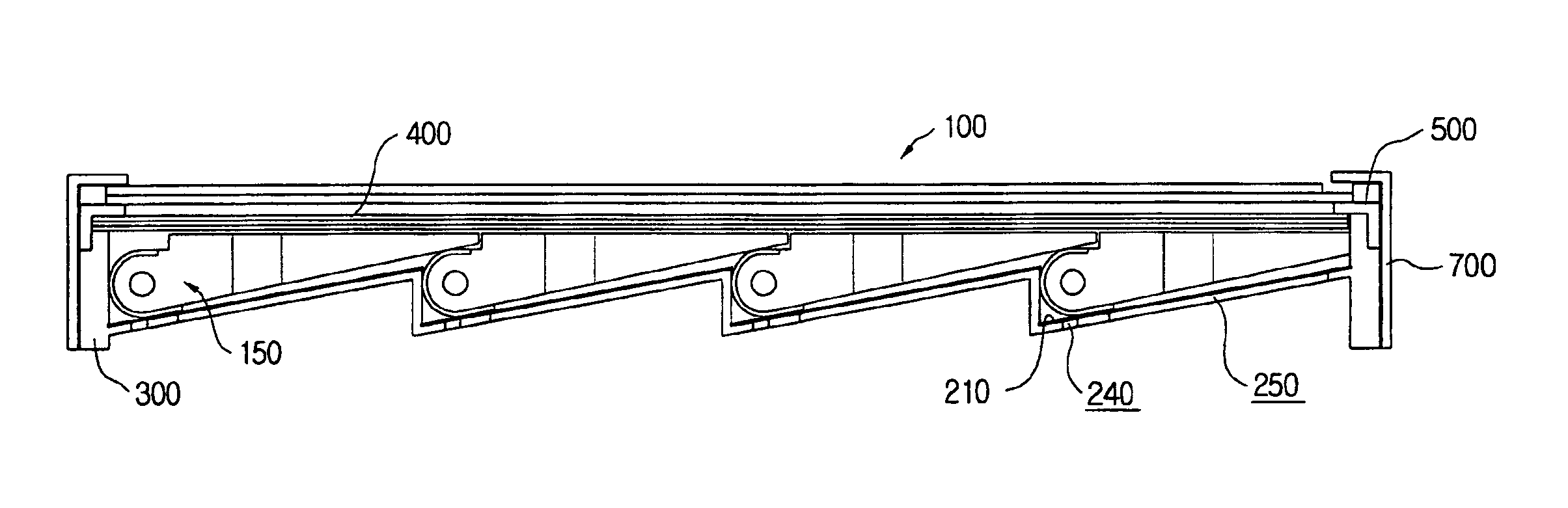
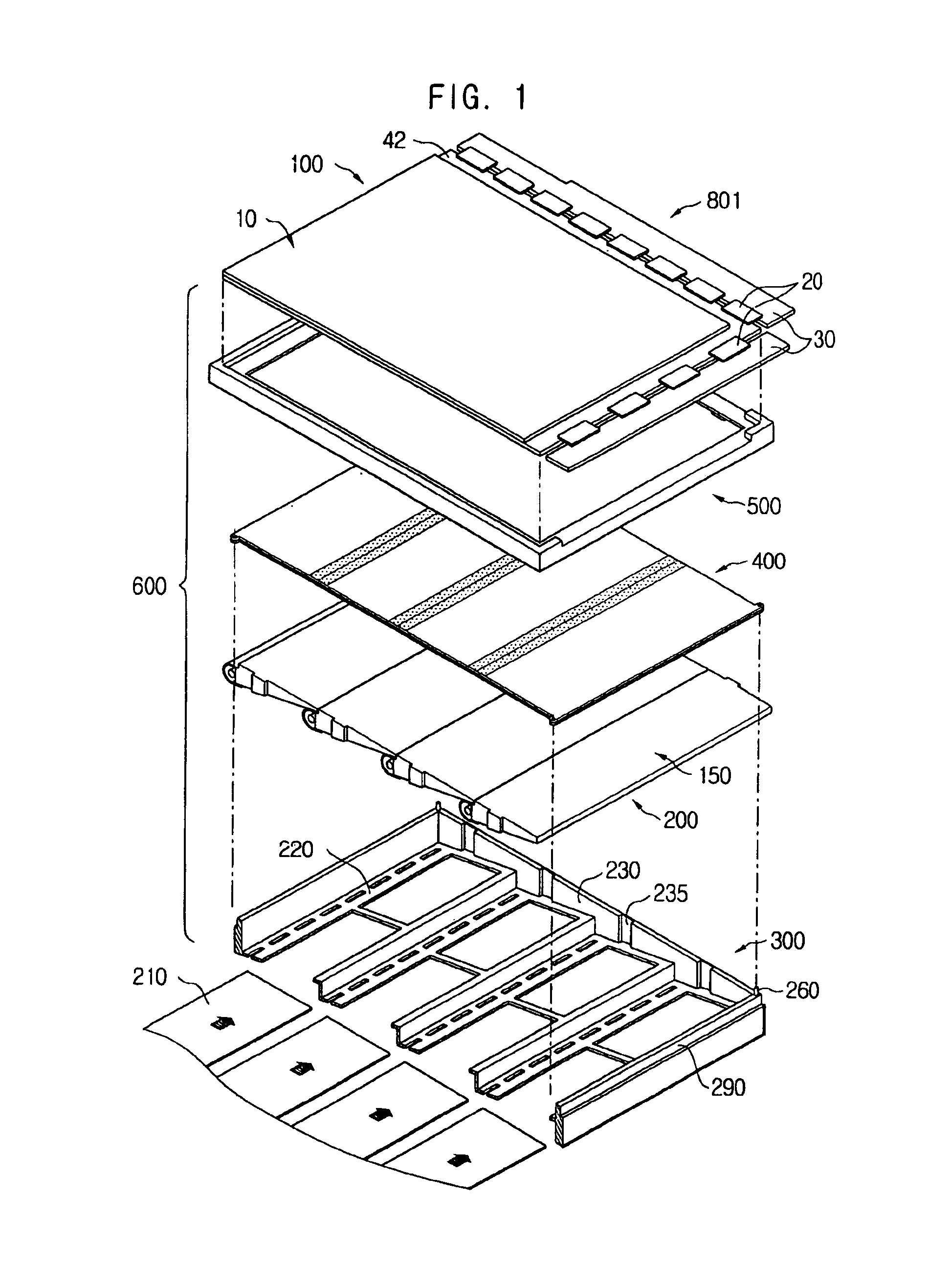
[0025]FIG. 1 is an exploded perspective view of the liquid crystal display according to a preferred embodiment of the present invention.

[0026]Referring to FIG. 1, the liquid crystal display 801 comprises a display unit 100, a back light assembly 600 and a chassis 700, on the whole.

[0027]The display unit 100 comprises a liquid crystal display (LCD) panel 10, a tape carrier package 20 and a printed circuit board (PCB) 30 having a driving signal generating part (not shown).

[0028]The LCD panel 10 includes a TFT substrate 2, a color filter substrate 4 and a liquid crystal layer interposed between the TFT substrate 2 and the color filter substrate 4.

[0029]The TFT substrate 2 includes a ...


PUM

PropertyMeasurementUnit
diagonal sizeaaaaaaaaaa
rectangular shapeaaaaaaaaaa
thicknessaaaaaaaaaa

Abstract

A liquid crystal display of a large screen size, a slim thickness and light weight is disclosed. The liquid crystal display includes a light supply unit group having at least two light guiding plates arranged in parallel and at least one lamp unit coupled to one side of the light guiding plate. A light control element is mounted on an upper surface of the light supply unit group, and uniformly controls luminance between the light guiding plate and the lamp unit. A reflective plate is disposed on a rear surface of the light supply unit group and has a shape corresponding to the rear surface of the light supply unit group. A back light assembly includes a receiving container that receives the light supply unit group, the light control element, and the reflective plate.

Description

[0001]This application is a continuation of Applicant's U.S. patent application Ser. No. 09 / 631,766 filed on Aug. 3, 2000, which has now become U.S. Pat. No. 6,580,477.BACKGROUND OF THE INVENTION[0002]1. Field of the Invention[0003]The present invention relates to a liquid crystal display (LCD), and more particularly to a liquid crystal display in which at least two or more light guiding plates are arranged in parallel, a lamp unit is disposed at one side of the light guiding plate or between the light guiding plates, thereby enhancing luminance of a large screen sized LCD, and enabling the LCD to have a uniform luminance and a compact size of a lighter weight.[0004]2. Description of the Related Art[0005]Generally, an LCD is a mostly used type of flat panel display. Especially, the small size, lighter weight and lower power consumption render the LCD to replace the traditional cathode ray tube (CRT).[0006]To display an image on the LCD panel, the LCD needs a light source called as b...

Claims


Application Information

Patent Timeline
Patent Type & Authority Patents(United States)
IPC IPC(8): F21V8/00G02F1/13G02F1/1335G02B6/00G02F1/1333G02F1/13357G09F9/00
CPCG02B6/0046G02B6/008G02B6/0088G02F1/133604G02F1/133605G02F1/133606G02F1/133608G02F1/133611G02B6/0068G02B6/0071G02F2001/133314G02F2001/133317G02F2001/133322G02F2001/133628G02F2201/36G02F2201/54G02F1/133322G02F1/133317G02F1/133314G02F1/133628G02F1/1335
Inventor CHO, CHUN-HYUN
Owner SAMSUNG DISPLAY CO LTD
Why Eureka
Try Eureka