Amplification with chalcogenide glass fiber

a technology of chalcogenide glass fiber and chalcogenide glass fiber, which is applied in the direction of instruments, optical elements, active medium materials, etc., can solve the problems of unreliability, large volume and technical complexity of lasers, and inability to meet the optical transmission window of silica glass fiber, etc., and achieves the effect of small volume, high efficiency and compact structur

Inactive Publication Date: 2005-08-09
THE UNITED STATES OF AMERICA AS REPRESENTED BY THE SECRETARY OF THE NAVY
View PDF3 Cites 32 Cited by
  • Summary
  • Abstract
  • Description
  • Claims
  • Application Information

AI Technical Summary

Benefits of technology

[0007]An object of this invention is an optical device which transmits in the wavelength region of up to about 15 μm that has high enough Raman gain, low enough loss, and / or narrow enough linewidth to enable Raman fiber lasers, amplifiers and a method for amplifying a light beam by the use of a chalcogenide glass gain medium / fiber.
[0010]Another object of this invention is the method for achieving high efficiency Raman fiber lasers and amplifiers using stimulated Raman scattering in infrared transmissive chalcogenide glass fibers to frequency shift a shorter wavelength pump beam to a longer wavelength Stokes beam.
[0011]Another object of this invention is an optical device that is smaller and more compact.

Problems solved by technology

To date, however, wavelengths have been limited to the optical transmission window of silica glass fiber, i.e., from the visible to about 2 μm.
Rare earth doped solid-state lasers are available for the 2-12 μm region; however, these lasers are bulky and technically complex.
Some experimental diode laser sources are available, however, they require cryogenic cooling and are unreliable.
To date, however, no fiber material has been shown to have high enough Raman gain, low enough loss, an / or narrow enough linewidth to enable Raman fiber lasers and amplifiers in these regions for these applications.

Method used


Image

  • Amplification with chalcogenide glass fiber
  • Amplification with chalcogenide glass fiber
  • Amplification with chalcogenide glass fiber

Examples


example 1

[0039]To demonstrate the Raman fiber amplifier and laser invention herein, Raman amplifier was fabricated operating at 1.56 μm in order to measure the Raman gain coefficient. FIG. 8 shows the experimental setup for the experiment.

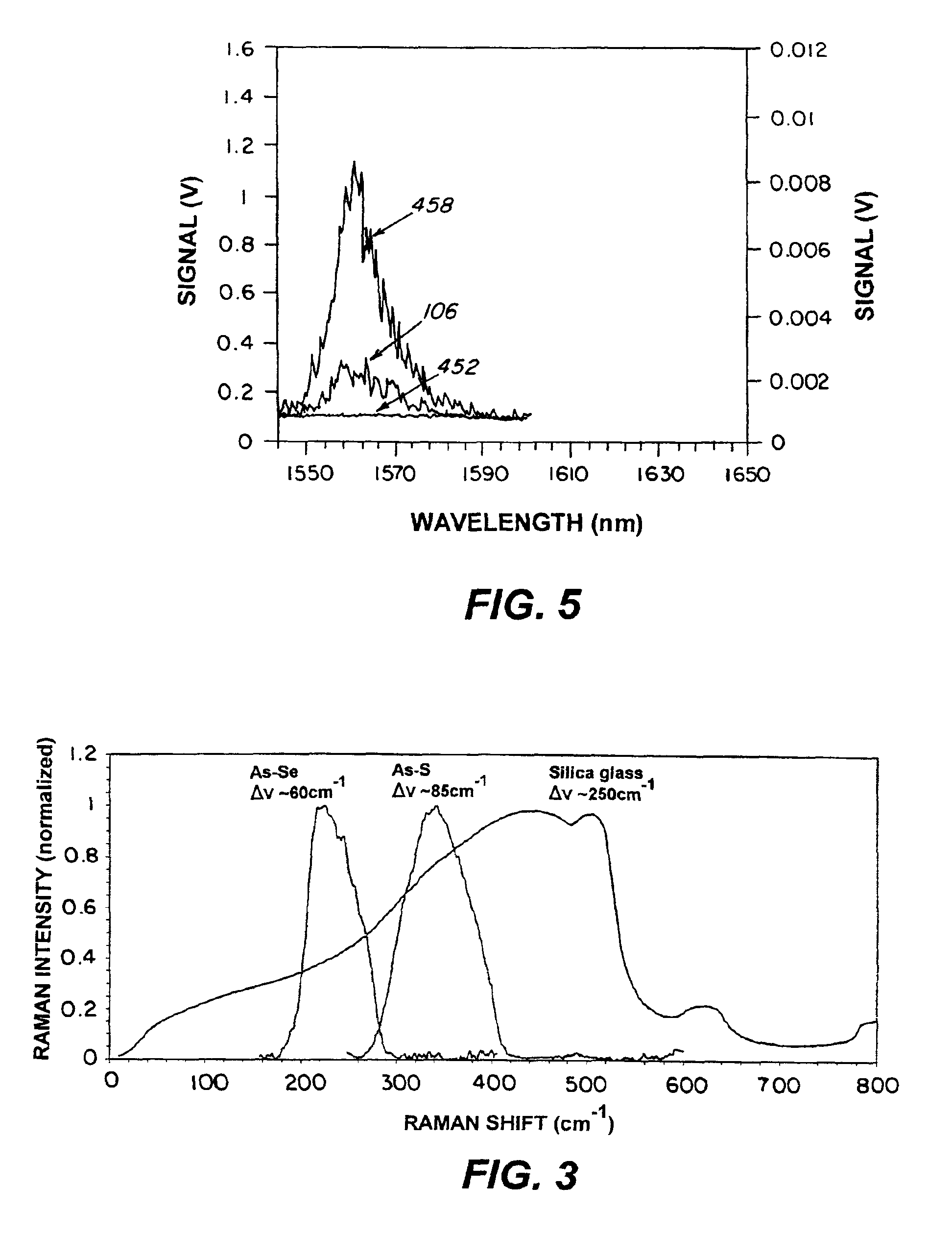
[0040]The device included a 1 meter section of As—Se fiber 210 with about 7 μm core and 100 μm cladding having NA of 0.45. The fiber loss was about 0.7 dB / m at 1.5 μm. The fiber was not single mode at 1.5 μm but was multimode since it could support up to nine modes. The device was pumped with Continuum Mirage OPO 212 at 1.56 μm with about 8 W of peak power in a 5 ns pulse. The signal source 214 was a 1.56 μm diode laser that was mixed with the pump laser using a 2×2 coupler 216. The amplified 1.56 μm signal was spectrally separated from the pump by a Jarrel-Ash ¼ meter monochromator 218 and detected with an InGaAs detector 220. The results are generally shown in FIG. 5. The unamplified diode laser signal without the pump was approximately 40 μV, which was a...

example 2

[0041]The demonstration of a fiber Raman amplifier of Ex. 1 shows the viability of the device. It has also been demonstrated that the device can operate farther into the IR by recording Raman signal at 1.91 μm under 1.83 μm pump and at 6.2 μm under 5.4 μm pump.


PUM


Abstract

This invention pertains to an optical device and method for using a chalcogenide glass waveguide to amplify a pump light beam by means of stimulated Raman scattering and obtaining a depleted pump light beam and an amplified beam at a wavelength higher than the wavelength of the depleted pump light beam.

Description

FIELD OF THE INVENTION[0001]This invention pertains to the use of a low phonon energy chalcogenide glass waveguide in conjunction with stimulated Raman scattering to amplify an optical signal in a glass waveguide.DESCRIPTION OF RELATED ART[0002]Fiber optic devices, such as amplifiers and lasers, based upon silica-based glasses, have many military and commercial applications. To date, however, wavelengths have been limited to the optical transmission window of silica glass fiber, i.e., from the visible to about 2 μm. Rare earth doped solid-state lasers are available for the 2-12 μm region; however, these lasers are bulky and technically complex. Some experimental diode laser sources are available, however, they require cryogenic cooling and are unreliable. Fiber lasers and amplifiers operating in the infrared region beyond 2 μm would offer many advantages over the current laser systems including compact size, stability, long life and ease of fabrication. Of particular interest is dev...

Claims


Application Information

Patent Timeline
Patent Type & Authority Patents(United States)
IPC IPC(8): H01S3/06H01S3/067H01S3/063H01S3/30H01S3/17
CPCH01S3/063H01S3/06754H01S3/0637H01S3/0675H01S3/171H01S3/302
Inventor SHAW, L. BRANDONSANGHERA, JASBINDER S.THIELEN, PETERAGGARWAL, ISHWAR D.
Owner THE UNITED STATES OF AMERICA AS REPRESENTED BY THE SECRETARY OF THE NAVY
Why Eureka
Try Eureka