

Amplification with chalcogenide glass fiber
Inactive Publication Date: 2003-01-16
THE UNITED STATES OF AMERICA AS REPRESENTED BY THE SECRETARY OF THE NAVY
View PDF0 Cites 14 Cited by
- Summary
- Abstract
- Description
- Claims
- Application Information
AI Technical Summary
Benefits of technology
[0007] An object of this invention is an optical device which transmits in the wavelength region of up to about 15 .mu.m that has high enough Raman gain, low enough loss, and / or narrow enough linewidth to enable Raman fiber lasers, amplifiers and a method for amplifying a light beam by the use of a chalcogenide glass gain medium / fiber.
[0010] Another object of this invention is the method for achieving high efficiency Raman fiber lasers and amplifiers using stimulated Raman scattering in infrared transmissive chalcogenide glass fibers to frequency shift a shorter wavelength pump beam to a longer wavelength Stokes beam.
[0011] Another object of this invention is an optical device that is smaller and more compact.
[0020] This invention describes a new approach for achieving high efficiency Raman glass fiber lasers and amplifiers in the infrared region. The approach involves utilizing Stimulated Raman Scattering (SRS) in infrared transmissive chalcogenide glass fibers to frequency shift a shorter wavelength pump beam to a longer wavelength Stokes beam. The use of chalcogenide glass fibers for Raman lasers and amplifiers not only allows high efficiency Raman conversion due to the high Raman cross-section of the material, but enables high average power sources in wavelength regions unreachable by current fiber laser sources based upon silica fibers due to the longer wavelength transparency of a chalcogenide glass. Amplification of intensity of an optical signal of at least 100 times can be achieved using the invention disclosed herein. By choosing a suitable pump wavelength, Raman lasers and amplifiers can be utilized to generate or amplify light in the wavelength region of about 1-15 .mu.m, limited only by the transmission of the chalcogenide glass. Furthermore, the high gain and narrow linewidth of the Raman line in a chalcogenide gain medium allow narrow band Raman amplification throughout the infrared region. The amplification method includes the steps of introducing the optical signal to be amplified into the coupler, introducing a pump optical signal into the coupling means, combining the optical signal and the pump optical signal, introducing the combined optical signal into the amplifier and amplifying the optical signal by stimulated Raman scattering.
[0025] The parameter that is determinant of the glass fiber length in an optical device is the Raman gain coefficient. For silica, the Raman gain coefficient is about 1.times.10.sup.-13 m / W and for a chalcogenide (As-Se), it is about 2.7.times.10.sup.-11 m / W, which is about 300 times larger than that for silica. For purposes herein, this means that when using a chalcogenide glass fiber, the fiber need be about {fraction (1 / 300)} as long when compared to a silica fiber to accomplish about the same amplification function for the same pump power. For example, silica glass fiber Raman amplifiers require several hundred meters of silica glass fiber and high pump power to produce useful gain. Chalcogenide glass fiber has a much higher Raman gain coefficient and therefore, allows for compact, high efficient optical devices with low thresholds for operation requiring more than one-hundred times less fiber.
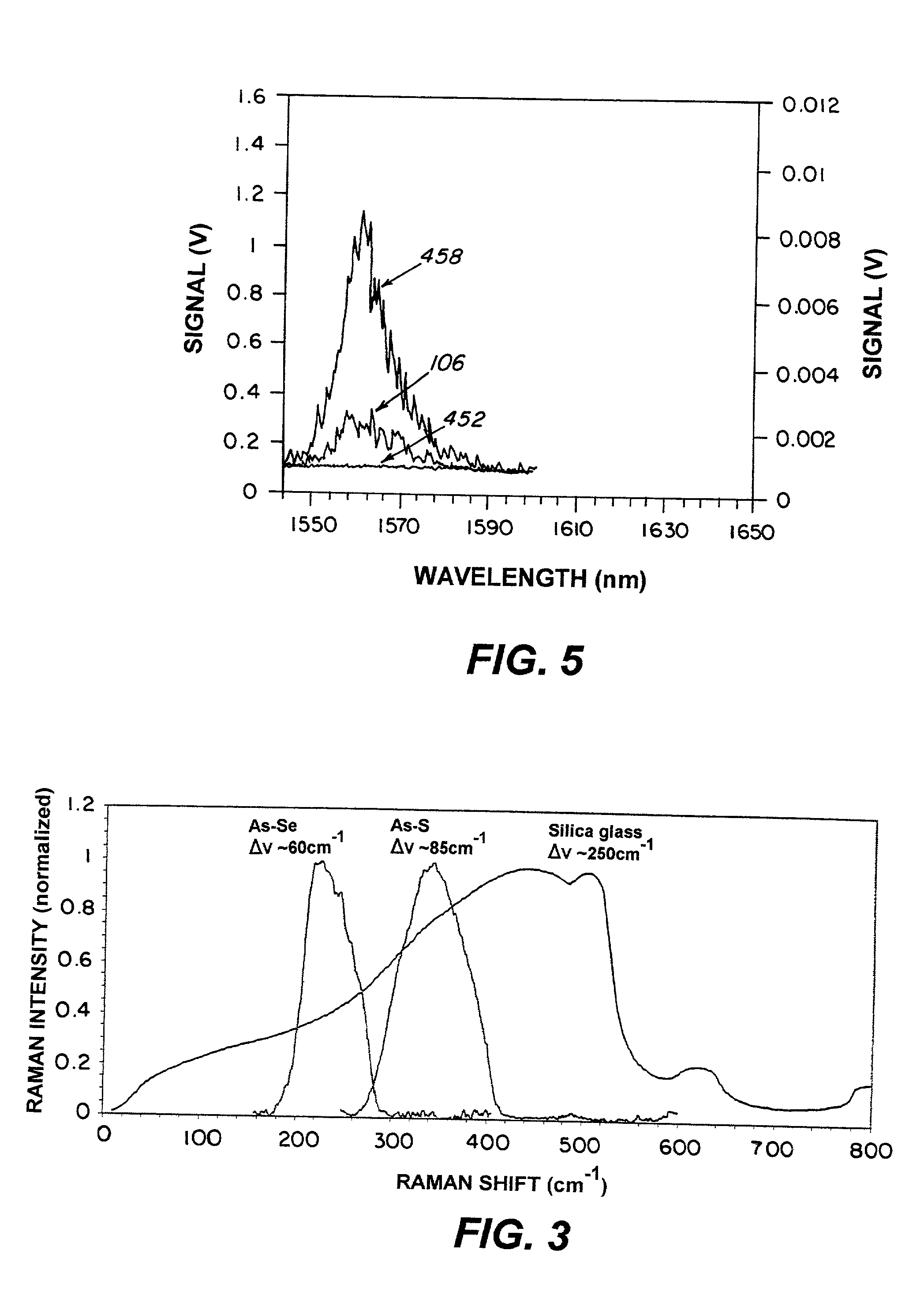
[0032] Assuming that equation (1), above, is obeyed, more than one optical signal can be amplified simultaneously. The signals can be at different wavelengths provided that they are within the bandwidth of the particular glass fiber used. FIG. 3 identifies a bandwidth of 250 cm.sup.-1 for silica glass fiber, a bandwidth of 60 cm.sup.-1 for chalcogenide As-Se glass fiber, and a bandwidth of 85 cm.sup.-1 for chalcogenide As-S glass fiber. Stimulated Raman scattering can amplify the signals falling within these particular bandwidths.
Problems solved by technology
To date, however, wavelengths have been limited to the optical transmission window of silica glass fiber, i.e., from the visible to about 2 .mu.m.
Rare earth doped solid-state lasers are available for the 2-12 .mu.m region; however, these lasers are bulky and technically complex.
Some experimental diode laser sources are available, however, they require cryogenic cooling and are unreliable.
To date, however, no fiber material has been shown to have high enough Raman gain, low enough loss, an / or narrow enough linewidth to enable Raman fiber lasers and amplifiers in these regions for these applications.
Method used
View moreImage
Smart ImageViewing Examples

Examples
example 2
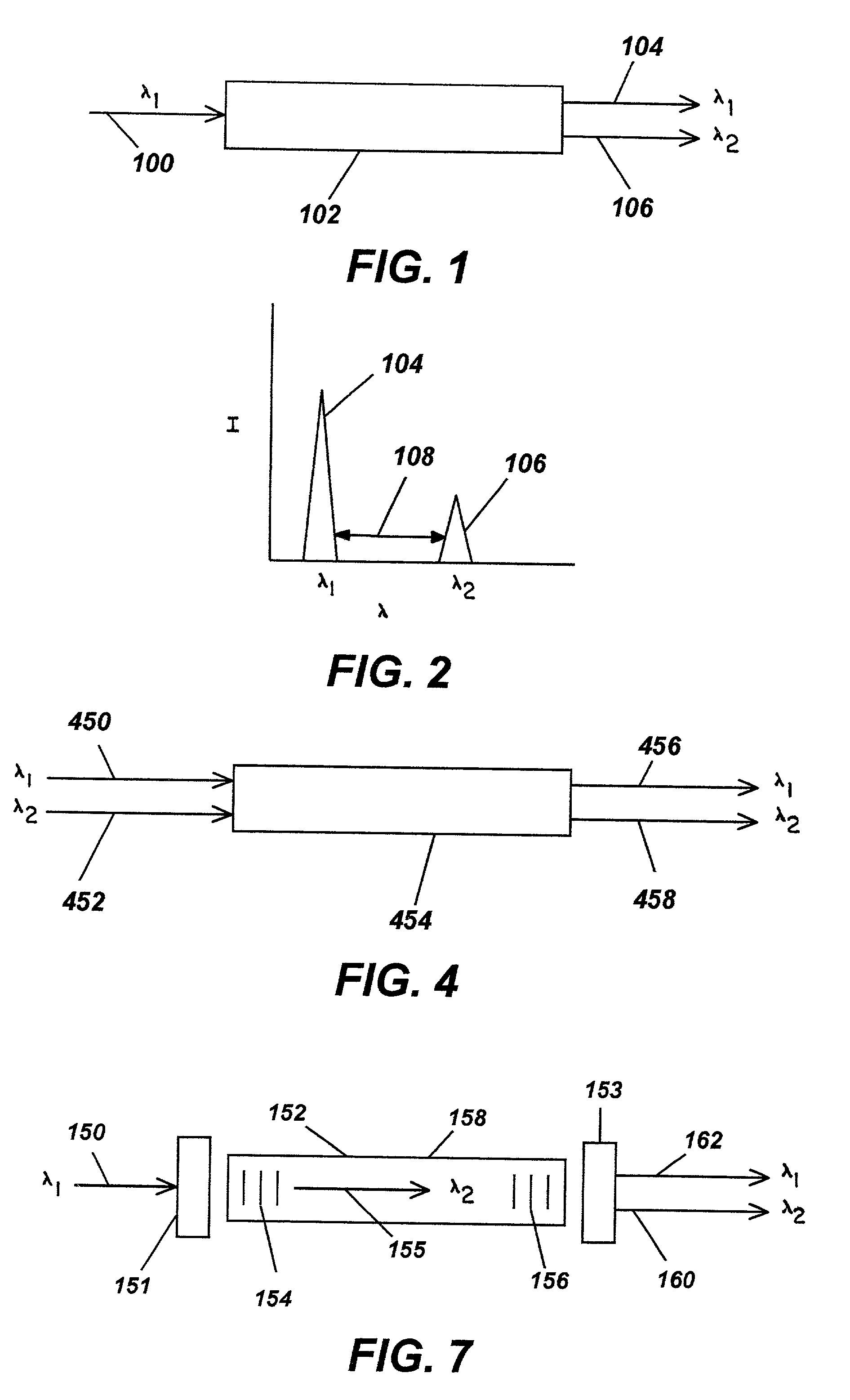
[0042] The demonstration of a fiber Raman amplifier of Ex. 1 shows the viability of the device. It has also been demonstrated that the device can operate farther into the IR by recording Raman signal at 1.91 .mu.m under 1.83 .mu.m pump and at 6.2 .mu.m under 5.4 .mu.m pump.
Login to View More PUM
 Abstract
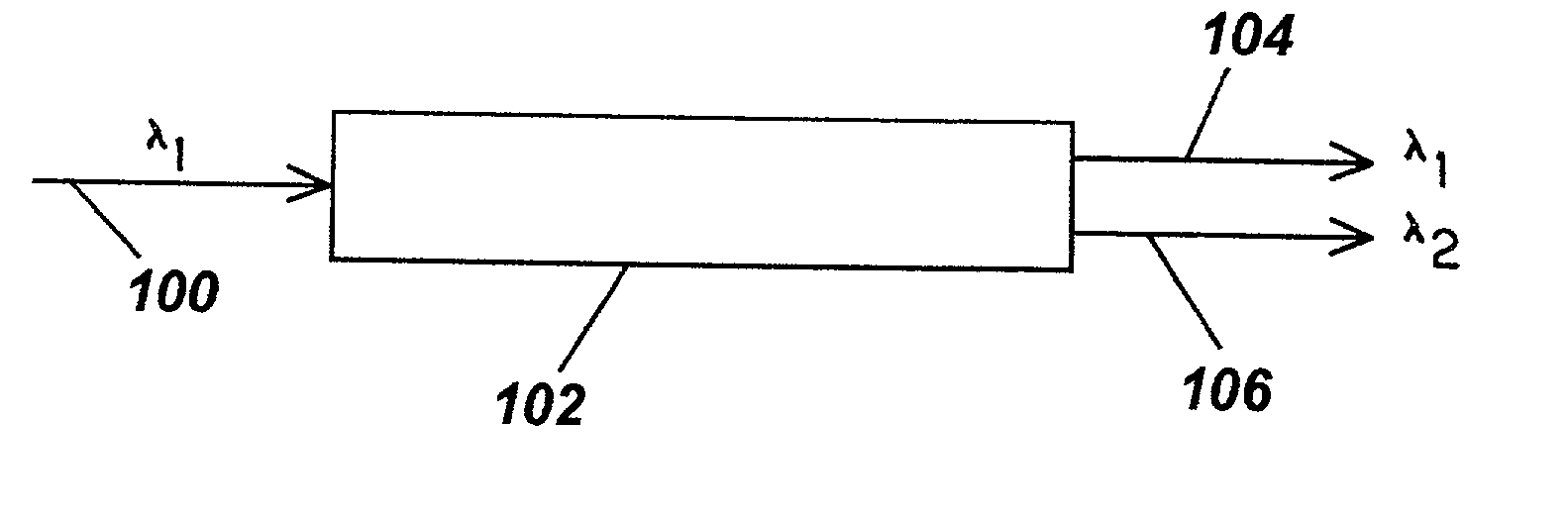
This invention pertains to an optical device and method for using a chalcogenide glass waveguide to amplify a pump light beam by means of stimulated Raman scattering and obtaining a depleted pump light beam and an amplified beam at a wavelength higher than the wavelength of the depleted pump light beam.
Description
[0001] This invention pertains to the use of a low phonon energy chalcogenide glass waveguide in conjunction with stimulated Raman scattering to amplify an optical signal in a glass waveguide.DESCRIPTION OF RELATED ART[0002] Fiber optic devices, such as amplifiers and lasers, based upon silica-based glasses, have many military and commercial applications. To date, however, wavelengths have been limited to the optical transmission window of silica glass fiber, i.e., from the visible to about 2 .mu.m. Rare earth doped solid-state lasers are available for the 2-12 .mu.m region; however, these lasers are bulky and technically complex. Some experimental diode laser sources are available, however, they require cryogenic cooling and are unreliable. Fiber lasers and amplifiers operating in the infrared region beyond 2 .mu.m would offer many advantages over the current laser systems including compact size, stability, long life and ease of fabrication. Of particular interest is developing las...
Claims
Login to View More Application Information
Patent Timeline
 IPC IPC(8): H01S3/063H01S3/067H01S3/17H01S3/30
CPCH01S3/063H01S3/0637H01S3/0675H01S3/06754H01S3/171H01S3/302
InventorSHAW, L. BRANDONSANGHERA, J. S.THIELEN, PETERAGGARWAL, ISHWAR D.
OwnerTHE UNITED STATES OF AMERICA AS REPRESENTED BY THE SECRETARY OF THE NAVY