Ice tool

Inactive Publication Date: 2005-08-16
HAHN GARY
View PDF13 Cites 11 Cited by
  • Summary
  • Abstract
  • Description
  • Claims
  • Application Information

AI Technical Summary

Benefits of technology

[0016]According to another aspect of the present invention, the ice tool is self contained and easily transportable. These features are advantageous to people who desire to onl

Problems solved by technology

Not having the proper tools detracts from the ability to ice fish, or at least detracts from the efficiency with which a person can set up and actively engage in the activity of ice fishing.
However, there are limits to the usefulness of ice augers.
For motorized ice augers in particular, it may be impractical to transport the ice auger to the desired fishing location, especially for people who walk to their fishing locations.
Also, sometimes the ice may not be thick enough to justify the labor required to transport the ice auger to the desired fishing location.
Further, ice augers are not suited for maintaining ice fishing holes, especially when a tip up is being used.
The chisel may be practical and effective for chiseling through ice that is only minimally thick, but problems can occur when using this tool to try to chisel through ice that is over about an inch thick.
This tool can be undesirably inaccurate, because it can be difficult to repeatedly strike the chisel of this tool in the same location when trying to chisel through the ice.
Doing this not only can damage the Chipper-Dipper, but also can be dangerous to the user.
Also, the handle is flimsy, which can further frustrate attempts to use the Chipper-Dipper to chip through a frozen surface.
While the spud bar is far more effective at breaking through thick ice than a Chipper-Dipper, there are undes

Method used


Image

  • Ice tool
  • Ice tool
  • Ice tool

Examples


Example

[0026]While the invention will be described in connection with one or more preferred embodiments, it will be understood that it is not intended to limit the invention to those embodiments. On the contrary, it is intended to cover all alternatives, modifications and equivalents as may be included within the spirit and scope of the invention as defined by the appended claims.

[0027]One surface on which the present invention can be used is an ice surface 5. The ice surface 5 can be any of thickness. However, in the preferred environment, the present invention is most useful with ice surfaces 5 having a thickness of about 4 inches or less. People 10 desiring to ice fish must first create a hole 6 through the ice surface 5. People 10 therefore grip the present invention with their hands 11 and then create the hole 6 through the ice surface 5. During the process of creating the hole 6, many ice pieces 7 are produced, which must be removed from the hole 6.

[0028]The present invention is pref...


PUM


Abstract

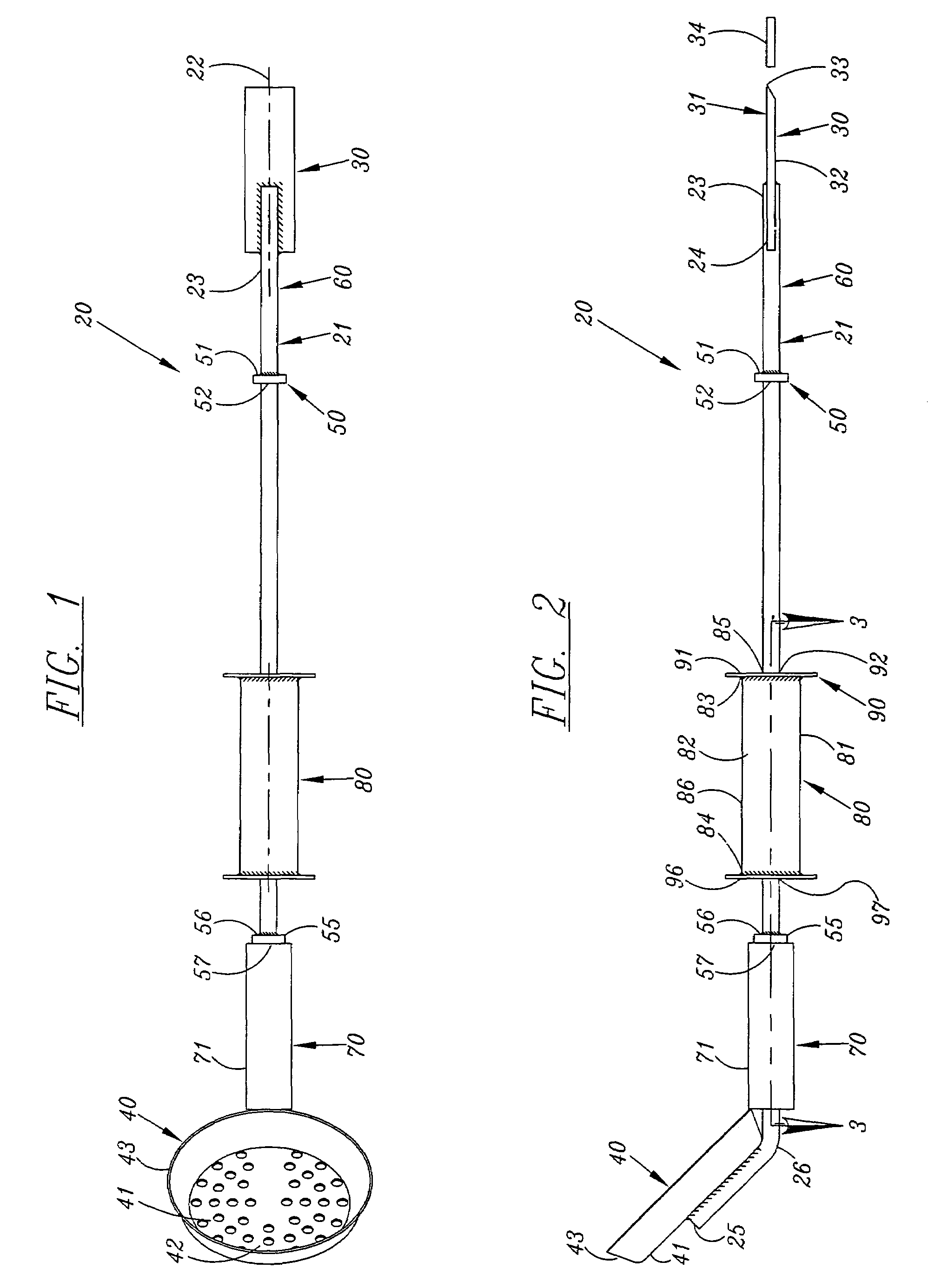
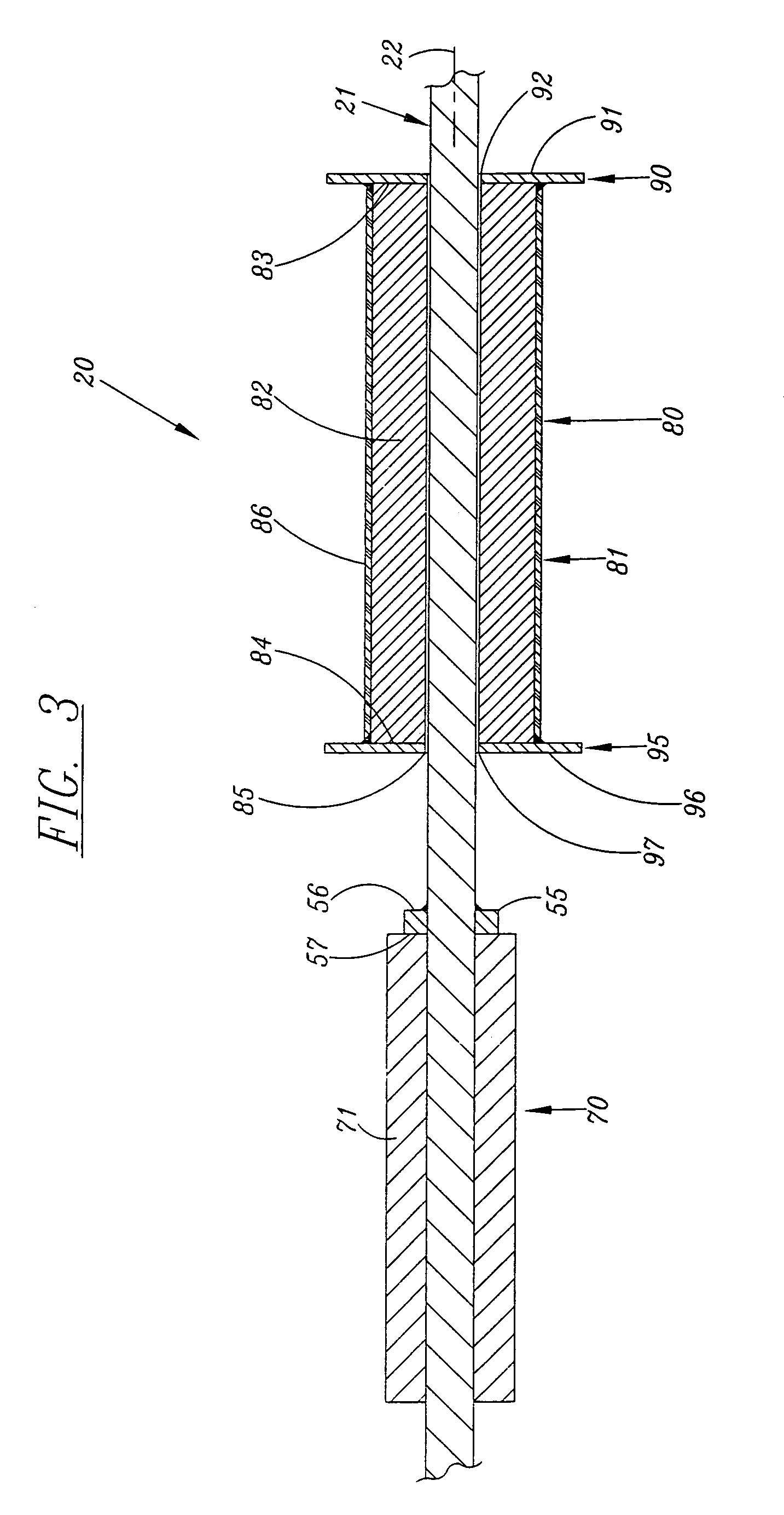
The present invention has a shaft with a chisel and a ladle at opposed ends. Two stops are welded to the shaft, and a slide assembly is located between the stops. A first handle is between the chisel and the first stop, and a second handle is between the ladle and the second stop. The slide assembly strikes the first stop to make the chisel break through the ice. The ladle is used to scoop out any pieces of ice that are in the hole. A rubber material is on the slide assembly and on the second handle to prevent the user's gloves from freezing thereon. The chisel can be driven into the frozen surface, but not through the frozen surface, to form an anchor. Removal of the anchor is accomplished by striking the slide assembly against the second stop.

Description

BACKGROUND OF THE INVENTION[0001]1. Field of the Invention[0002]The present invention relates generally to a tool, and more particularly to a tool comprising a shaft with a chisel and a ladle on opposed ends of the shaft, and a slide assembly therebetween for causing the chisel to impact a frozen surface to create a hole through the frozen surface.[0003]2. Description of the Related Art[0004]People desiring to ice fish need many tools, such as a tool for creating a hole through the ice, and tools for catching fish. Not having the proper tools detracts from the ability to ice fish, or at least detracts from the efficiency with which a person can set up and actively engage in the activity of ice fishing.[0005]People commonly use ice augers to create an ice fishing hole. Many companies manufacture and sell ice augers, and they are well understood in the art. Ice augers perform well for creating a hole through ice, even when the ice has a thickness of several feet or more. However, ther...

Claims


Application Information

Patent Timeline
IPC IPC(8): B25F1/00A01K97/01B25D7/00
CPCA01K97/01B25D7/00B25D2222/15B25D2250/241
Inventor HAHN, GARY
Owner HAHN GARY
Why Eureka
Try Eureka