Tool for shearing bolts

a technology of shearing bolts and tools, applied in the direction of screws, load-modified fasteners, fastening means, etc., can solve the problem of not being able to tolerate the length of screws projecting from an exposed surface, and achieve the effect of sufficient stability

a technology of shearing bolts and tools, applied in the direction of screws, load-modified fasteners, fastening means, etc., can solve the problem of not being able to tolerate the length of screws projecting from an exposed surface, and achieve the effect of sufficient stability

US6928900B2Inactive Publication Date: 2005-08-16V O DESIGN & INNOVATION

Image

  • Tool for shearing bolts
  • Tool for shearing bolts
  • Tool for shearing bolts

Examples


Embodiment Construction

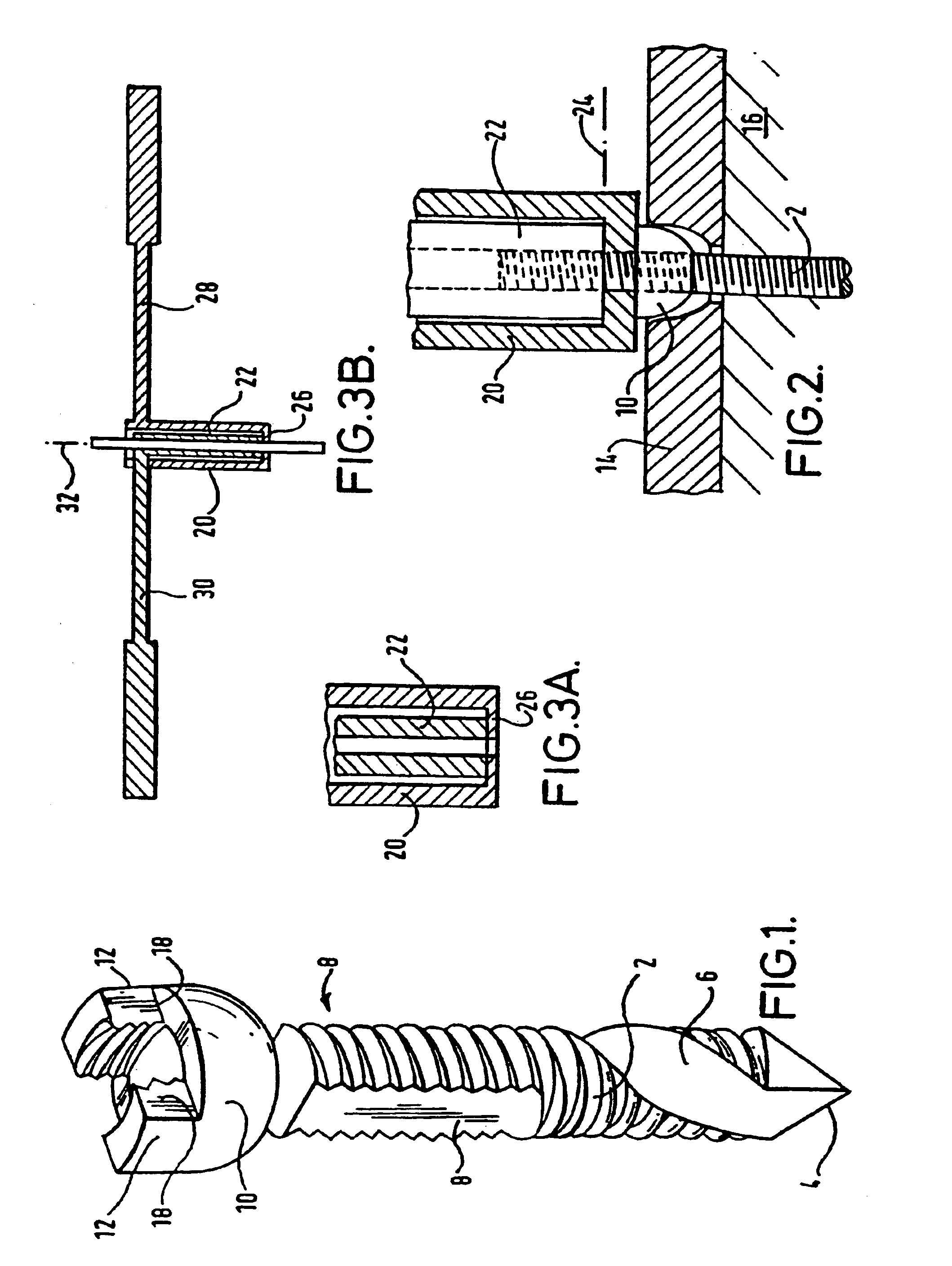
[0025]The assembly shown in FIG. 1 consists of a screw 2 having a sharp end 4 from which a removal duct 6 extends to flanks 8 cut parallel into opposite sides of the screw. As can be seen, the flanks are cut well below the root of the screw thread. The nut 10 has a generally hemi-spherical base with two upstanding projections 12 on the inner surfaces whereof are formed internal screw threads corresponding to the external thread on the shaft 2. The peripheral extent of each thread section on the projections 12 of the nut is less than the notional periphery length of the thread cut away to form each flank 8 on the shaft 2. Thus, with the respective threads misaligned, the nut 10 can move translationally along the shaft 2 without any engagement between the threads. However, this is not essential. The assembly does of course function quite effectively with a full thread on the nut, requiring rotation of the nut to effect its translational movement, and this can be preferred in some circ...


PUM


Abstract

A tool for breaking a shaft includes two aligned tubular elements (20, 22), each having an end portion for receiving a contiguous length of the same shaft (2). Means are provided for locking each end portion against rotation relative to the shaft length received therein, and the elements are adapted for rotation relative to one another with the end portions so locked, to relatively twist the shaft lengths and shear the lengths at the interface between them. The element end portions will normally have juxtaposed faces, and it is preferred that the faces are moved towards each other during the relative rotation and as the shaft lengths are twisted relative to each other. This assists in achieving a substantially planar face at the fracture plane. A compressible washer may be disposed between the juxtaposed faces. This can stabilize the moving parts as the shaft is broken, although normally screw threads on the tubular elements will effect the movement of the element. towards each other, and this in itself may provide sufficient stability.

Description

RELATED APPLICATION[0001]This is a continuation application of U.S. patent application Ser. No. 09 / 762,029, now abandoned which is a §371 of International Patent Application No. PCT / GB99 / 02558, filed 4 Aug. 1999, claims priority from British Application No. GB9816962.6, filed 4 Aug. 1998 entitled “Tool for Shearing Bolts”. These applications are incorporated herein by reference.TECHNICAL FIELD[0002]This invention relates to the breaking of shafts, nomally metallic shafts, in which contiguous shaft lengths are twisted relative to one another to break the shaft along a fracture plain. The invention has particular application to lockable screw assemblies in which a shaft is broken at a fracture plane substantially aligned to the exposed surface of a nut located and typically locked thereon. This Application is of especial value in surgical applications where such a screw assembly is used as a cortical bone screw whose length is immediately adaptable to an individual situation.BACKGROUN...

Claims


Application Information

Patent Timeline
16 Aug 2005
Publication
US6928900B2
IPC
A61B17/68; A61B17/88; A61B17/86; F16B31/00; F16B31/02; B26D3/16; A61B17/58; F16B35/04
CPC
A61B17/8605; A61B17/8863; A61B17/8665; F16B31/021
Inventors
DALL, VAGN-ERIK; REED, DAVID J.