Vibration sensor assembly and method for bark controller

a vibration sensor and controller technology, applied in the field of vibration sensor assembly and method of bark controller, can solve the problems of general disturbance, unsatisfactory welfare of dogs themselves and nearby people, and the battery life of some prior bark limiters is undesirabl

Active Publication Date: 2005-08-16
GARMIN
View PDF10 Cites 94 Cited by
  • Summary
  • Abstract
  • Description
  • Claims
  • Application Information

AI Technical Summary

Benefits of technology

[0014]It is another object of the invention to provide a bark control device that discriminates between various sounds and vibrations that a dog might make and avoids applying electrical stimulus to the dog in response to any sound other than a valid bark sound.
[0016]It is another object of the invention to provide an improved bark control device that provides a convenient and effective self-test capability.

Problems solved by technology

This is undesirable with respect to the welfare of the dogs themselves and nearby people.
Similar problems occur in neighborhoods in which there are dogs that are kept outside at night: if one dog starts barking others are likely to join in, causing a general disturbance.
However, the large size and weight of the assignee's Bark Limiter product have limited it to use on medium-sized and large-sized dogs.
The battery life of some prior bark limiters has been undesirably short because dog owners often find it convenient to leave the devices in a “power on” condition for long periods of time, even during times when the dog is not likely to be barking.

Method used


Image

  • Vibration sensor assembly and method for bark controller
  • Vibration sensor assembly and method for bark controller
  • Vibration sensor assembly and method for bark controller

Examples


Embodiment Construction

[0032]A preferred embodiment of a dog bark limiter of the present invention includes an improved vibration transducer structure for transmitting vibrations from the dog's neck through a plastic surface membrane of the bark limiter housing. In the described embodiment, a motion detector detects characteristic motion of the dog's neck produced as a result of barking and in response automatically powers up the circuitry from a very low power stand by operating condition. A technique of “valid” bark detection executes a capture and compare program to accomplish the function of, in effect, generating a frequency spectrum of the received sound and comparing it with a predetermined frequency spectrum to determine if the received sound constitutes a “valid” bark. A self-test mode is provided to self-test or verify operability of the neck motion sensor and the sound vibration sensor.

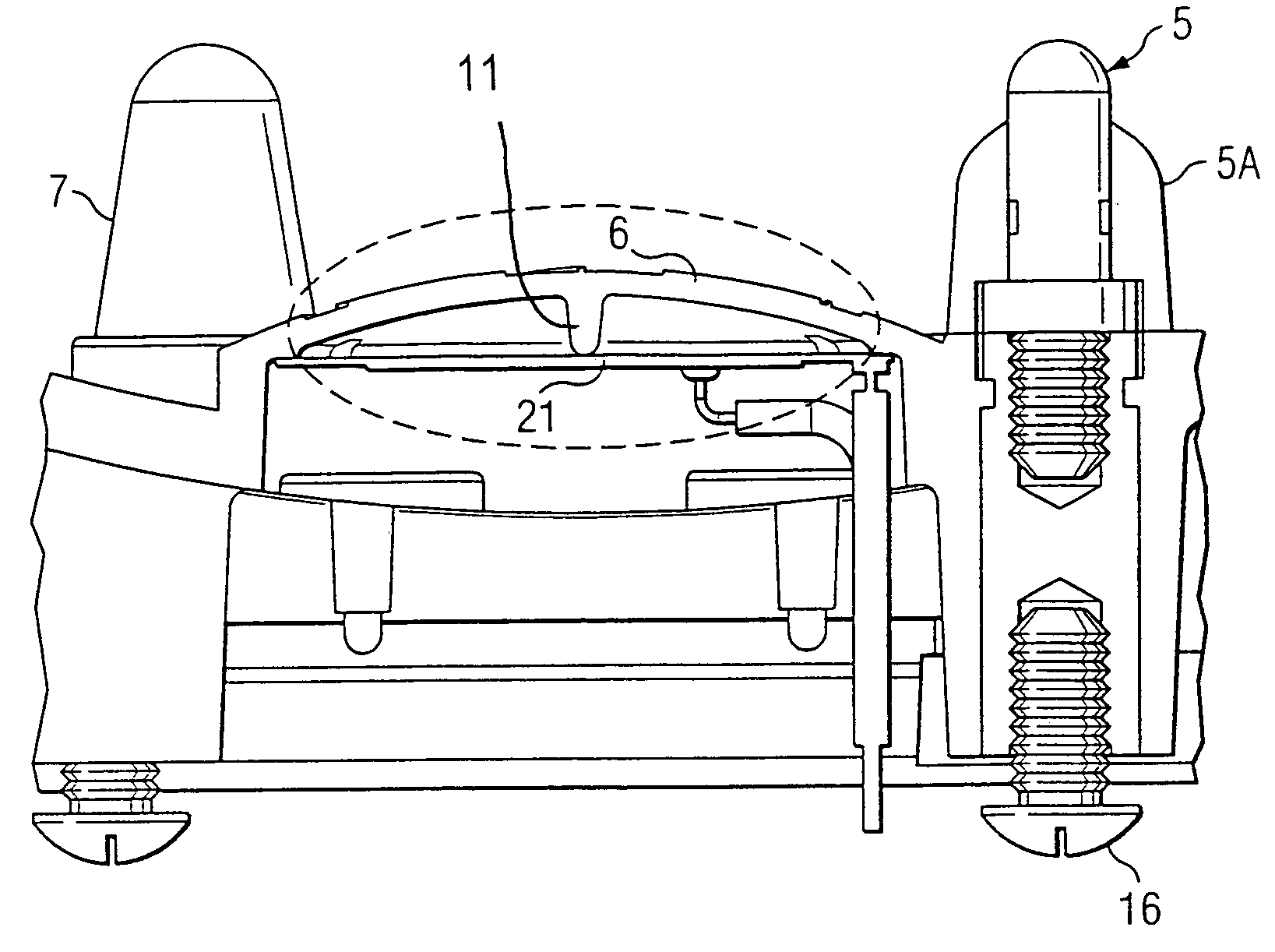
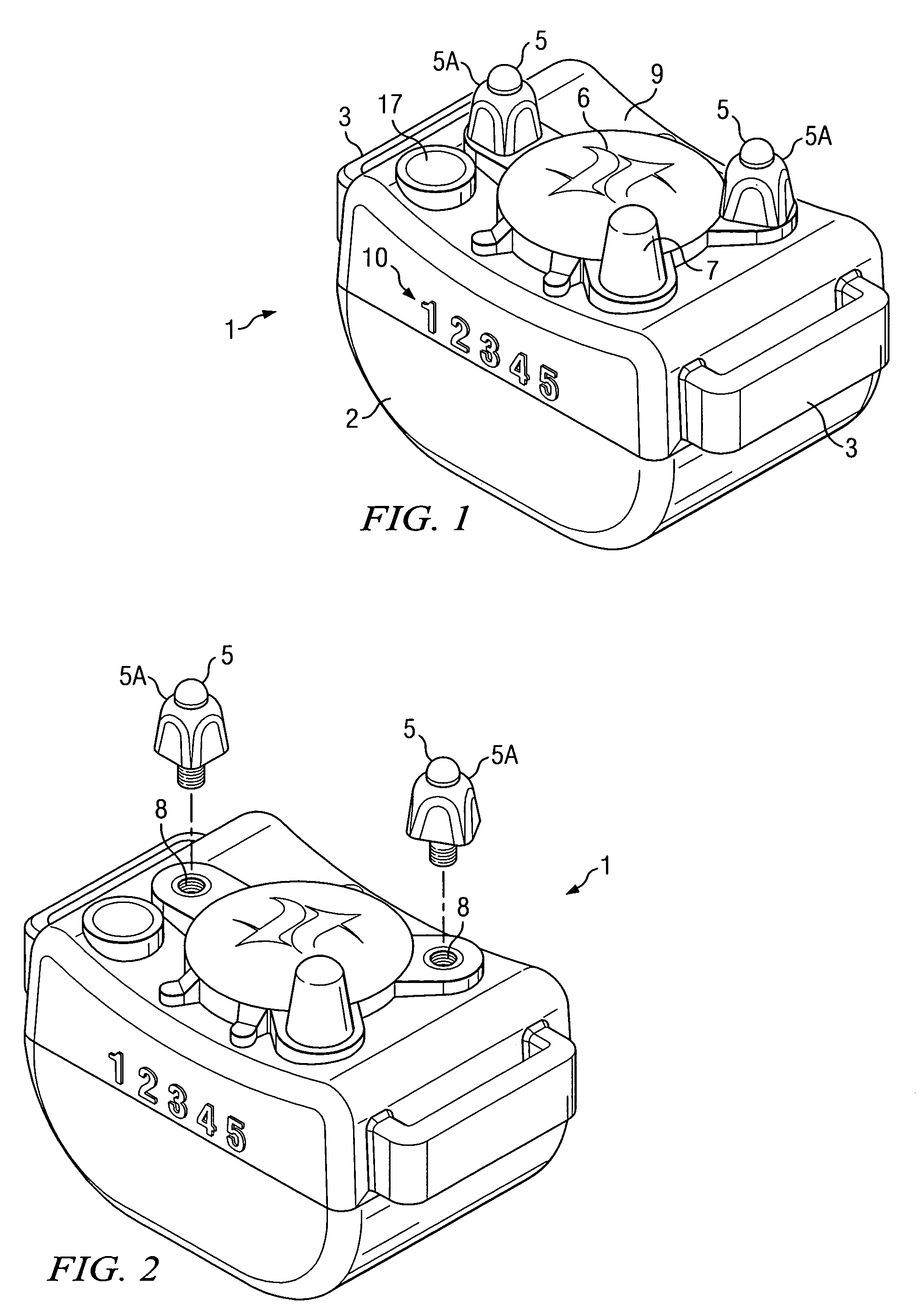
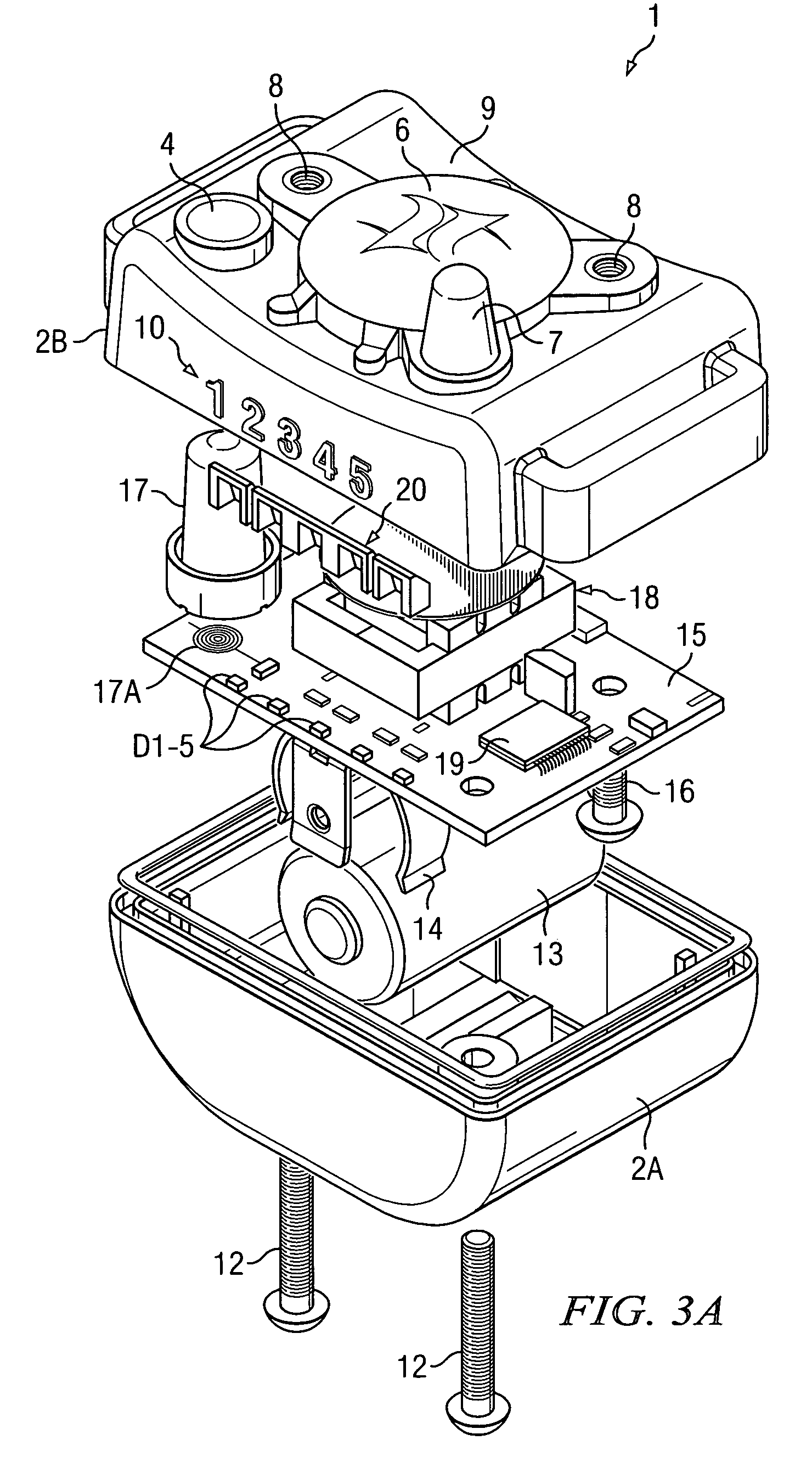
[0033]Referring to FIGS. 1, 2, 3A and 3B, bark limiter 1 includes a housing 2 having a lower section 2A and an...


PUM


Abstract

A dog bark limiter includes a housing (2) supported against the dog's skin by a strap, stimulus electrodes (5), and a sensor (6) for producing signals in response to vocalizing by the dog. The sensor includes a membrane (6) supported by the surface (9) for efficiently transmitting sound energy through the housing and a rigid nipple (11) engaging the membrane. Control circuitry in the housing has an input coupled to an output of the transducer and output terminals coupled to produce aversive stimulus signals between the first and second electrodes in response to the signals produced in response valid barking by the dog. A motion detector (40) produces a motion detection signal in response to a characteristic movement of the portion of dog that accompanies barking by the dog and aids in detecting a valid bark. A controller (33) executes a frequency capture routine to produce a frequency spectrum of the dog's vocalizations and compares it with a valid bark spectrum to determine if the vocalization constitutes a valid bark.

Description

BACKGROUND OF THE INVENTION[0001]The present invention relates generally to collar-mounted electronic “bark limiter” or dog bark training devices, and more particularly to improvements therein which allow improved, more reliable sensing of vibration due to barking of the dog. The invention also relates to improved determination of what constitutes valid barking.[0002]A variety of electronic dog training collars have been utilized for applying electrical shock and / or audible stimulus to a dog when it barks. In many situations it is highly desirable to prevent individual dogs or groups of dogs from barking excessively. For example, one dog's barking in a kennel is likely to stimulate other dogs to bark. This is undesirable with respect to the welfare of the dogs themselves and nearby people. Similar problems occur in neighborhoods in which there are dogs that are kept outside at night: if one dog starts barking others are likely to join in, causing a general disturbance.[0003]The clos...

Claims


Application Information

Patent Timeline
Patent Type & Authority Patents(United States)
IPC IPC(8): A01K15/00A01K15/02
CPCA01K15/022Y10S119/908
Inventor CRIST, TIMOTHY J.DUNCAN, TIMOTHY T.NAPOLEZ, FRANCISCO J.
Owner GARMIN
Why Eureka
Try Eureka