Method for upward growth of a hydraulic fracture along a well bore sandpacked annulus

a technology of hydraulic fracture and upward growth, which is applied in the direction of borehole/well accessories, survey, construction, etc., can solve the problems of frac-treatment cost, repetitive, and long time-consuming, and achieve the effect of reducing the number of fractures, and improving the quality of the hydraulic fractur

Inactive Publication Date: 2005-08-16
HILL GILMAN A
View PDF4 Cites 13 Cited by
  • Summary
  • Abstract
  • Description
  • Claims
  • Application Information

AI Technical Summary

Benefits of technology

[0019]Still another objective of the invention is to use the fluidized bed process to build a near-continuous sandpacked annulus in an uncemented cased well bore for any purpose such as for control of production of sand, or other reservoir rock fragments, from unconsolidated, or poorly consolidated reservoir rocks.
[0020]The subject method of creating the tall frac includes creating a linear-sourced, cylindrical stress field by maneuvering the intersection of two independent friction-controlled pressure gradients of a frac pad fluid. The intersection of these two frac pad fluid pressure gradients can be controlled when the frac pad fluid traverses along a well bore sandpacked annulus. The first pressure gradient is created by controlling the fluid flow rate and the consequent, friction pressure loss in t

Problems solved by technology

However, each stage of this type of multistage frac program has to be separately isolated, perforated, a

Method used


Image

  • Method for upward growth of a hydraulic fracture along a well bore sandpacked annulus
  • Method for upward growth of a hydraulic fracture along a well bore sandpacked annulus
  • Method for upward growth of a hydraulic fracture along a well bore sandpacked annulus

Examples


Embodiment Construction

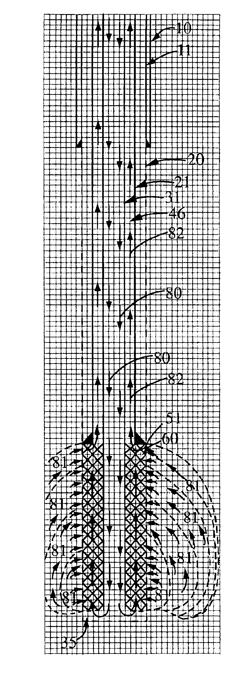
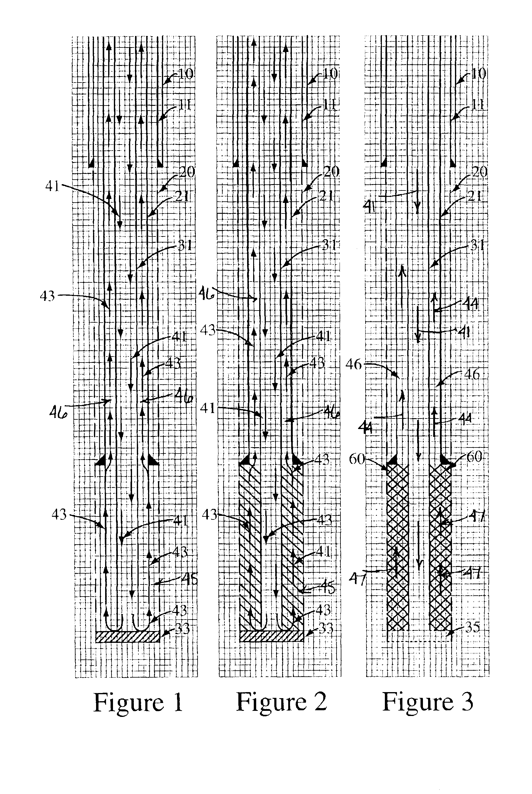
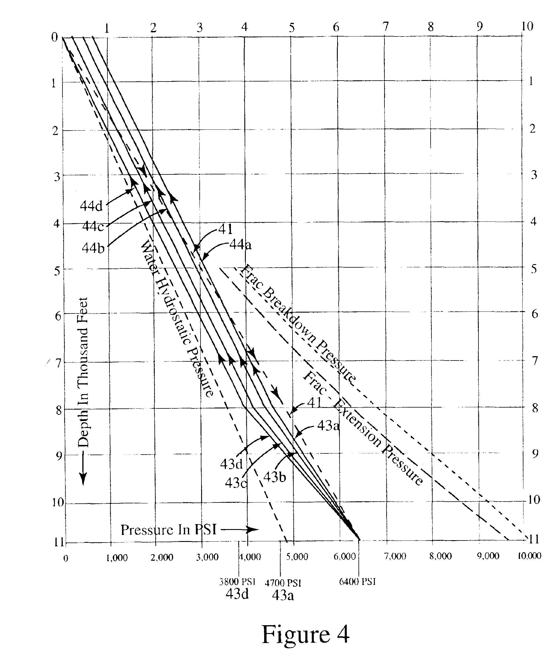
[0043]The present invention provides a method for creating a tall frac extending vertically through a multiplicity of sand and shale formations. The tall frac method provides an intersection between two different fluid friction controlled pressure gradients. Frac pad fluid flow is used to traverse vertically along a well bore sandpacked annulus over an interval of the sand and shale formations and encompassed by the tall frac. The present invention provides a controlled fluidized bed method for creating the well bore sandpacked annulus used for creating the tall frac.

[0044]In FIGS. 1, 2, and 3, the mechanical configuration of the well bore and casing is illustrated for providing the fluid circulation paths needed to build a sandpacked annulus 60, a tall frac, and filling the tall frac with proppant sand using a fluidized bed methodology.

[0045]As shown in these drawings, a large-sized surface hole 10 is drilled and a surface casing 11 is set and cemented in place. A normal diameter d...


PUM


Abstract

A method for outward and upward growth of a hydraulic fracture along a well bore sandpacked annulus and over a selected rock formation interval along a length of a well bore. The fracture is created along the interval encompassing a multitude of oil and gas saturated sand formations and intervening silt and shale formations for more efficiently producing oil and/or gas from the formations. The method includes creating a linear sourced, cylindrical, stress field by maneuvering an intersection of a fluid friction controlled first pressure gradient and a second pressure gradient of a frac pad fluid traversing through a well bore sandpacked annulus and a hydraulic frac in the adjacent rock formation interval. The first pressure gradient is created by controlling a fluid flow rate of the frac pad fluid through a portion of the sandpacked annulus located above the top of an upwardly propagating hydraulic fracture. The first pressure gradient is substantially greater than an average gradient of rock formations frac-extension pressure gradient. The second pressure gradient is equal to or less than the average frac-extension pressure gradient and is created by a friction loss of a volume flow rate of the frac pad fluid flowing through combined parallel paths of the sandpacked annulus and the hydraulic fracture propagating outward and upward in the adjacent rock formation.

Description

[0001]This application is based on a provisional patent application filed on Jul. 8, 2002, Ser. No. 60 / 393,817, by the subject inventor, and having a title of “METHOD FOR UPWARD GROWTH OF A HYDRAULIC FRACTURE ALONG A WELL-BORE ANNULUS SAND PACK”BACKGROUND OF THE INVENTION[0002](a) Field of the Invention[0003]This invention relates to a method of hydraulic fracturing of an oil and / or gas well bore and more particularly, but not by way of limitation, to a method of creating an effective hydraulic fracture over a selected interval along a length of a well bore. The fracture along the interval encompasses a multitude of oil and / or gas-saturated sand formations and intervening silt and shale formations. The new method of hydraulic fracturing is used for the purpose of more efficiently producing oil and / or gas from all of these formations.[0004]The subject hydraulic fracturing method uses an uncemented, well bore sandpacked annulus to produce a controllable and movable line source of a fr...

Claims


Application Information

Patent Timeline
IPC IPC(8): E21B43/25E21B43/26E21BE21B47/00
CPCE21B43/04E21B43/26
Inventor HILL, GILMAN A.
Owner HILL GILMAN A
Why Eureka
Try Eureka