Magnetic lock

a magnetic lock and magnetic technology, applied in the field of magnetic locks, can solve the problems of the hook, and other associated problems, and achieve the effects of simple construction, easy opening of the display, and easy damage to the slide lock

Inactive Publication Date: 2005-08-16
INVENTEC CORP
View PDF4 Cites 150 Cited by
  • Summary
  • Abstract
  • Description
  • Claims
  • Application Information

AI Technical Summary

Benefits of technology

[0008]A primary object of the present invention is to provide a magnetic lock mountable on an electronic device capable of opening or closing. The magnetic lock comprises an upper magnetic plate formed on an upper housing of the electronic device and a lower magnetic plate formed on a lower housing of the electronic device. The electronic device is automatically locked because magnetic members of the upper magnetic plate attract magnetic members of the lower magnetic plate having a polarity different from that of the magnetic members of the upper magnetic plate when the upper housing is covered the lower housing. Alternatively, a user can move the upper magnetic plate about the lower magnetic plate a predetermined distance to repel the magnetic members of the upper magnetic plate from the magnetic members of the lower magnetic plate having the same polarity as that of the magnetic members of the upper magnetic plate to unlock the electronic device. By utilizing the present invention, the above drawbacks of the prior art can be overcome. These drawbacks are that the protruding hooks are not aesthetic, it is not easy to open the display for unlocking the notebook computer, and it is often that a user may use a great force to open the display not being aware that the hooks are not disengaged from the slots, resulting in a great possibility of easily damaging the slide lock, the hooks, and other associated. The magnetic lock of the present invention also has the following advantages. It can be realized in a simple construction, simple manufacturing, and low cost. Further, the magnetic lock of the present invention is compact, simple and easy in operation, and ergonomic.

Problems solved by technology

These drawbacks are that the protruding hooks are not aesthetic, it is not easy to open the display for unlocking the notebook computer, and it is often that a user may use a great force to open the display not being aware that the hooks are not disengaged from the slots, resulting in a great possibility of easily damaging the slide lock, the hooks, and other associated.

Method used


Image

  • Magnetic lock
  • Magnetic lock
  • Magnetic lock

Examples


Embodiment Construction

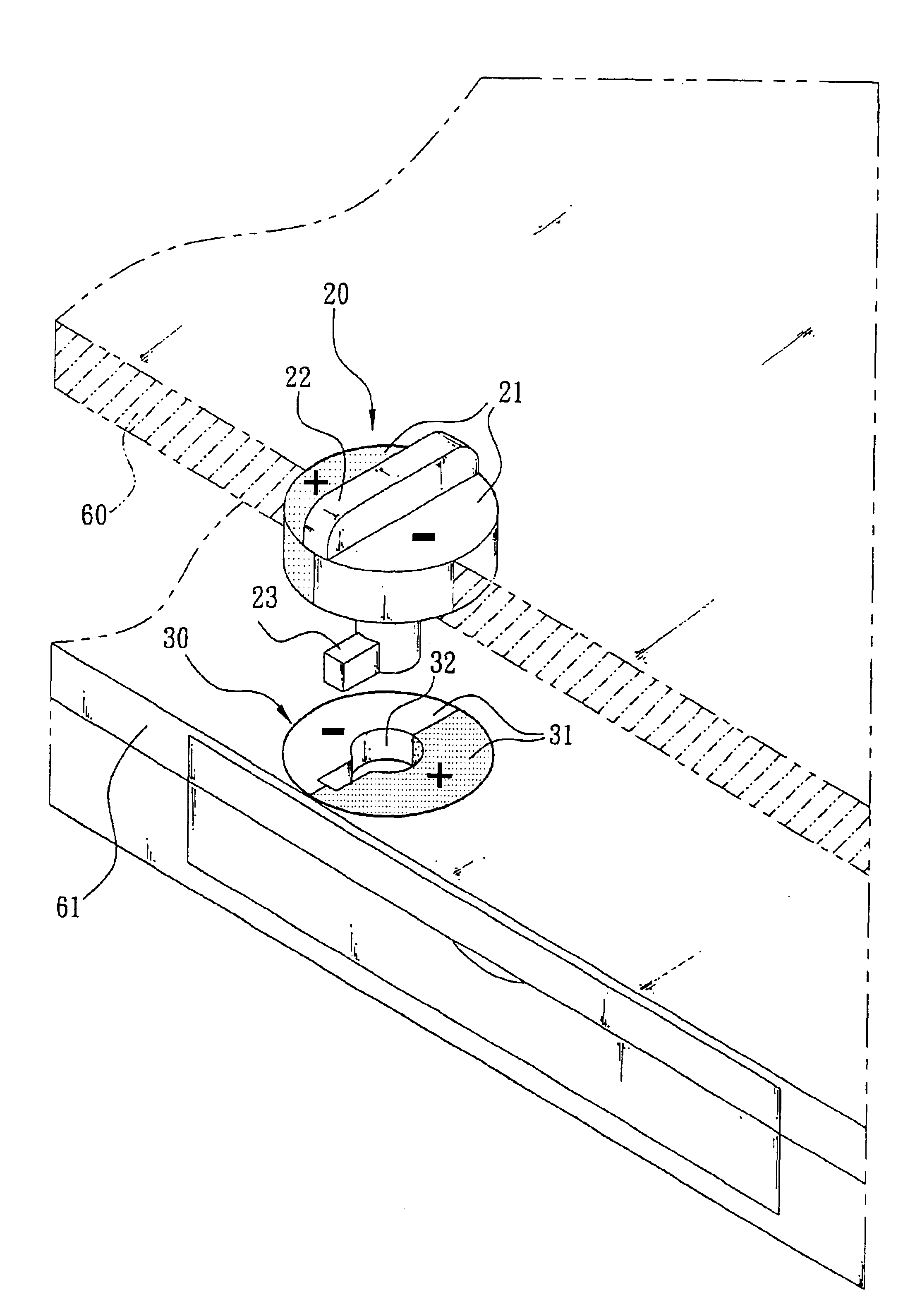
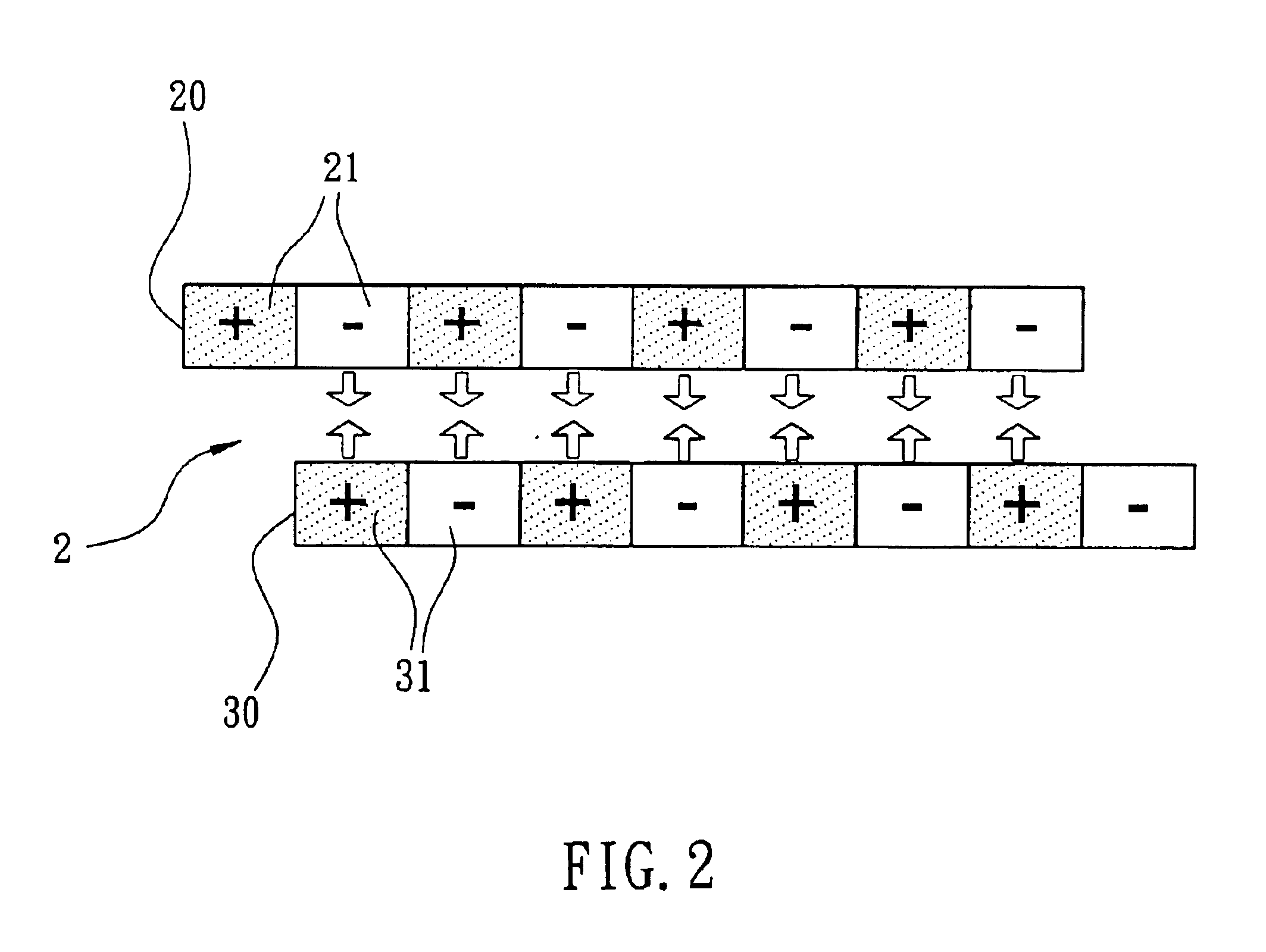
[0016]Referring to FIG. 2, there is shown a magnetic lock 2 in accordance with a first preferred embodiment of the invention. The magnetic lock is adapted to mount on an electronic device (e.g., notebook computer, palm computer, or the like) capable of opening or closing. The magnetic lock 2 comprises an elongate, rectangular upper magnetic plate 20 and an elongate, rectangular lower magnetic plate 30. The upper magnetic plate 20 comprises a plurality of alternate magnetic members 21 of positive polarity (+) and magnetic members 21 of negative polarity (−) from one end to the other end. Each of the magnetic members 21 of positive polarity (+) and the magnetic members 21 of negative polarity (−) is formed of a magnetic pad 21 in this embodiment. As shown in FIG. 2, similar to the upper magnetic plate 20, the lower magnetic plate 30 comprises a plurality of alternate magnetic members 31 of positive polarity (+) and magnetic members 31 of negative polarity (−) from one end to the other...


PUM


Abstract

The present invention is to provide a magnetic lock mountable on an electronic device, which comprises an upper and a lower magnetic plates respectively formed on an upper and a lower housings of the electronic device, enabling the electronic device to be automatically locked due to the attraction between a plurality of magnetic members disposed on the corresponding positions of the upper and lower magnetic plates having different polarities when the upper housing is covered the lower housing. Alternatively, when the upper magnetic plate is moved a predetermined distance, the corresponding magnetic members on the upper and lower magnetic plates are in turn having the same polarity to repel with each other, enabling the upper and lower housings of the electronic device to be automatically unlocked.

Description

FIELD OF THE INVENTION[0001]The present invention relates to locks and more particularly to a magnetic lock having a particular application in electronic device.BACKGROUND OF THE INVENTION[0002]A variety of electronic and information products are developed due to the fast progress in electronics and computer technology. Correspondingly, more and more users become more critical with respect to the functions and the quality of the products. The increasing consumer demand with respect to manufacturers of portable computer, particularly notebook computer, is very significant.[0003]The trend of developing notebook computers is slimness, compactness, and lightweight in consideration of weight and size. Moreover, an all-in-one notebook computer is constantly being sought. Nowadays, all-in-one notebook computers are dominant type of portable computers. It is understood that the notebook computer market is very competitive. Fortunately, a wide variety of notebook computers are available for ...

Claims


Application Information

Patent Timeline
Patent Type & Authority Patents(United States)
IPC IPC(8): E05C19/00E05C19/16G06F1/16
CPCE05C19/16G06F1/1616G06F1/1679Y10T292/11
Inventor CHEN, HSIANG
Owner INVENTEC CORP
Why Eureka
Try Eureka