Switch matrix

a switch matrix and matrix technology, applied in the field of switches, can solve the problems of difficult removal of the attaching plate b>6/b>, and achieve the effect of convenient installation and replacemen

Inactive Publication Date: 2005-08-16
LEGRAND HOME SYST
View PDF201 Cites 35 Cited by
  • Summary
  • Abstract
  • Description
  • Claims
  • Application Information

AI Technical Summary

Benefits of technology

[0009]In view of the above described state of the art, the present invention seeks to realize one or more of the following objects and advantages.
[0010]It is a primary object of the present invention to provide a switch matrix which is simple in design and manufacture.
[0012]It is a further object of the present invention, in accordance with one aspect thereof, to provide a switch matrix which allows the keys to be arranged in different configurations using differing numbers of keys.
[0013]It is an additional object of the invention, in accordance with one aspect thereof, to provide a switch matrix which allows the keys to be easily installed and replaced without damaging the matrix.

Problems solved by technology

Removal of the attaching plate 6 is a difficult task which may require the services of a professional or use of specialized equipment since the attaching plate 6 is fixed to the housing 4 and is not designed to be easily removed without damaging the attaching plate 6 or the housing 4.

Method used


Image

  • Switch matrix
  • Switch matrix
  • Switch matrix

Examples


Embodiment Construction

[0028]For the purposes of promoting an understanding of the principles in accordance with the invention, reference will now be made to the preferred embodiments illustrated in the drawings and specific language will be used to describe the same. It will nevertheless be understood that no limitation of the scope of the invention is thereby intended. Any alterations and further modifications of the inventive features illustrated herein, and any additional applications of the principles of the invention as illustrated herein, which would normally occur to one skilled in the relevant art and having possession of this disclosure, are to be considered within the scope of the invention claimed.

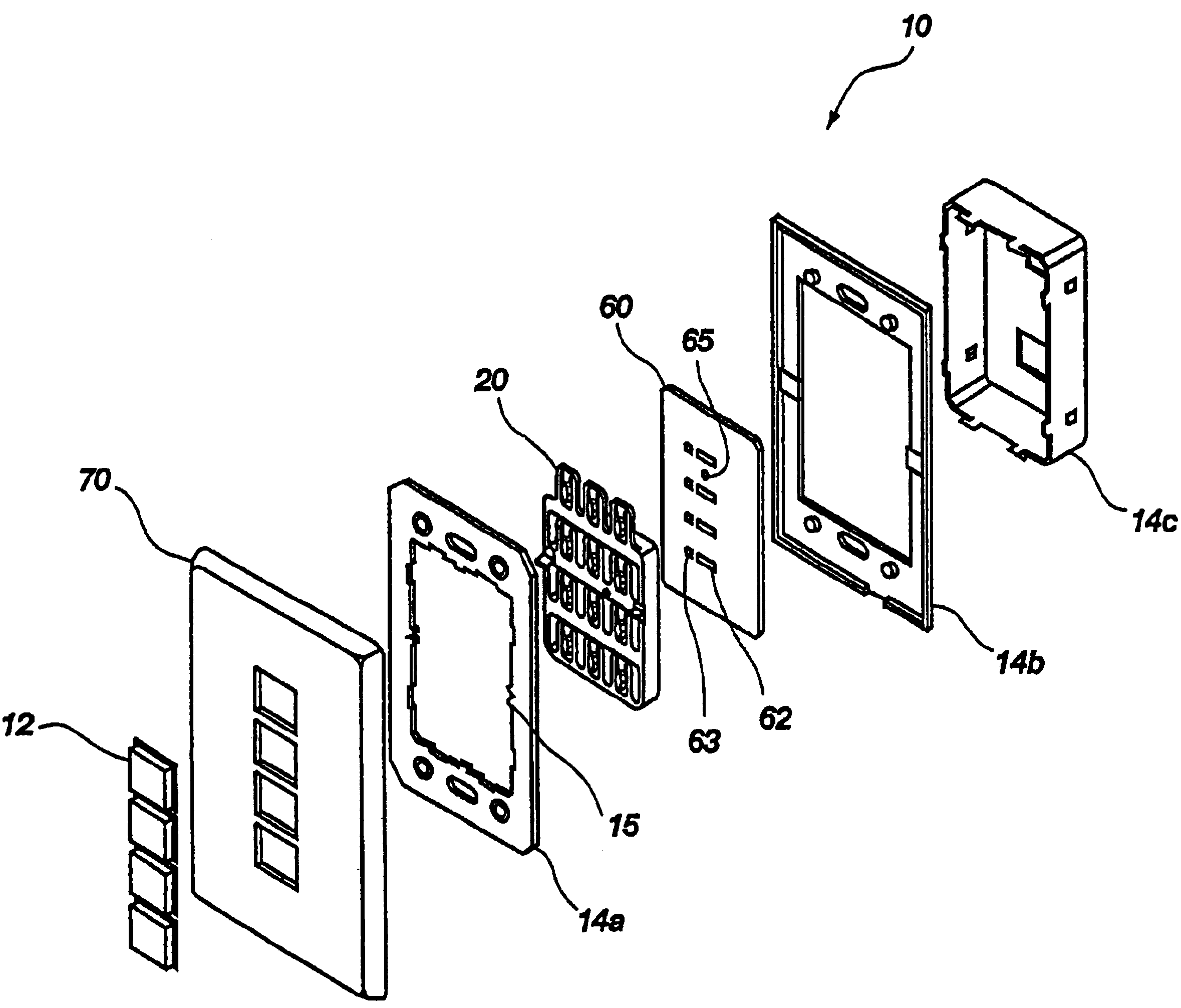
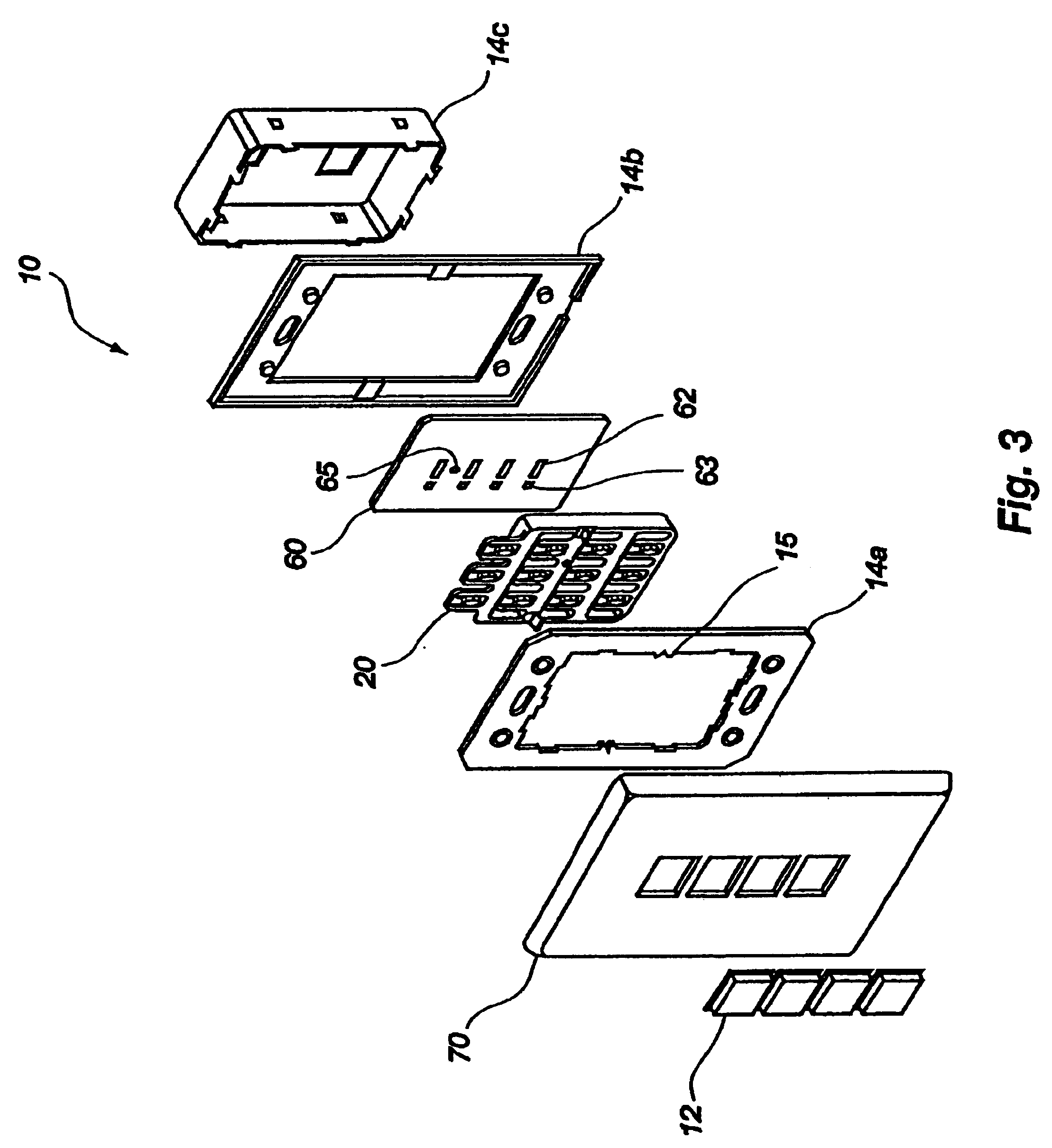
[0029]Referring now to FIG. 3, an exploded perspective view of a keypad, generally indicated at 10, is shown including a preferred embodiment of a switch matrix 20 of the present invention. The keypad 10 may be used as a user interface for home automation and security systems, for example. The keypad...


PUM

PropertyMeasurementUnit
sizesaaaaaaaaaa
resilientaaaaaaaaaa
friction fitaaaaaaaaaa

Abstract

A switch matrix is disclosed for keypads used in devices such as primary control points for automation systems in homes vehicles, or businesses. The switch matrix preferably includes a support frame for supporting a grid of key positioning members arranged in a series of rows and columns. The key positioning members each preferably include cantilevers which can be deflected by pressing the keys to activate switches associated with the keypad. The cantilevers preferably have knobs which are received in corresponding openings in the keys so that the keys can be removably attached to the cantilevers with a compression fit. This allows keys of different sizes and shapes to be easily attached to the keypad in various configurations without the need for different attaching devices for each situation.

Description

CROSS-REFERENCE TO RELATED APPLICATIONS[0001]This application is a continuation of 10 / 024,129, filed Dec. 17, 2001, now U.S. Pat. No. 6,660,948 which claims the benefit of U.S. Provisional Application No. 60 / 272,020, filed Feb. 28, 2001, which is hereby incorporated by reference herein in its entirety, including but not limited to those portions that specifically appear hereinafter.BACKGROUND OF THE INVENTION[0002]1. The Field of the Invention[0003]The present invention relates generally to keypad devices, and more particularly, but not necessarily entirely, to a switch matrix which allows the use of variable key positions and key sizes on the keypad.[0004]2. Description of Related Art[0005]It is common practice to provide keypads consisting of one or more keys arranged for entry of data or performing functions such as activating switches. Keypads are used for various types of electronic devices such as user interfaces for home automation and security systems, calculators, telephone...

Claims


Application Information

Patent Timeline
Patent Type & Authority Patents(United States)
IPC IPC(8): H01H13/70
CPCH01H13/70H01H2207/048H01H2219/062H01H2221/056H01H2221/066H01H2223/058Y10T29/49105H01H2237/004H01H2239/016H01H2300/03Y02B90/224Y04S20/14H01H2229/022Y02B90/20
Inventor CLEGG, PAUL T.DAY, WALLACE E.
Owner LEGRAND HOME SYST
Why Eureka
Try Eureka