
Linear synchronous motor with multiple time constant circuits, a secondary synchronous stator member and improved method for mounting permanent magnets

a technology of synchronous motors and circuits, applied in the field of linear synchronous motors, can solve problems such as inability to use existing solid induction types, and achieve the effect of accurate pole pitch spacing

Active Publication Date: 2005-08-16
VELOCITY MAGNETICS
View PDF15 Cites 32 Cited by
  • Summary
  • Abstract
  • Description
  • Claims
  • Application Information

AI Technical Summary

Benefits of technology

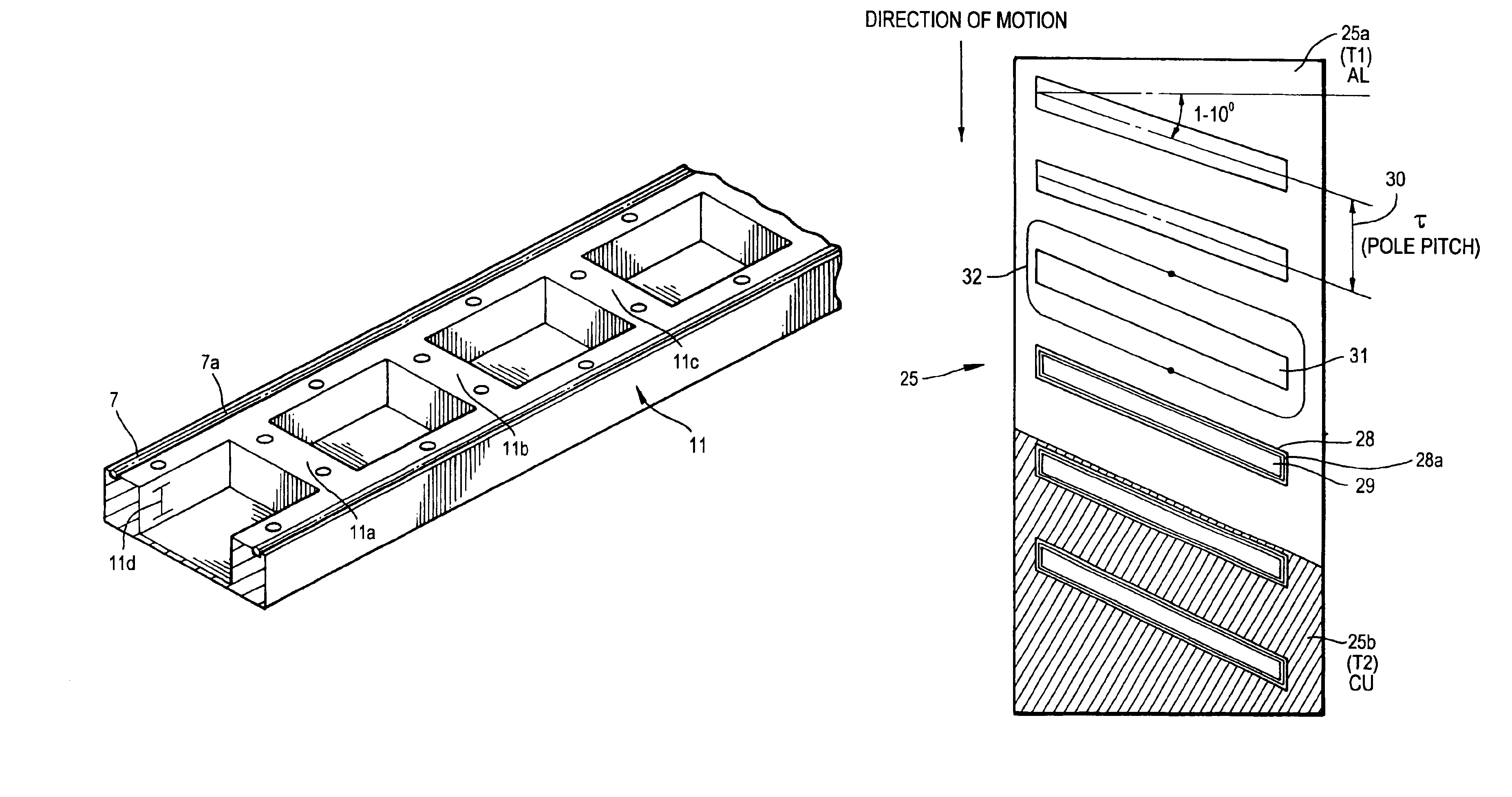
[0006]In an embodiment, the invention provides a synchronous linear secondary stator member that is electrically synchronous which will accompany a primary member, the synchronous linear permanent magnet motor. The system of the present invention provides a variable stator electrical frequency as the primary permanent magnet synchronous motor enters the synchronous linear stator member at a particular velocity, wherein the electrical frequency along the synchronous linear stator member diminishes as vehicle velocity fades. The stator member has narrow slots which provide a pole pitch spacing that corresponds with the pole pitch spacing of the permanent magnet linear synchronous primary member. The slotting of the secondary stator causes the electrical currents in the stator to move through discrete pathways during transient dynamic excitation. The electrical frequency can be adjusted by increasing or decreasing the identical pole pitch spacing of both the primary and secondary members, thereby allowing a variable braking force throughout the entire active braking area.

Problems solved by technology

This is not possible with existing solid induction type, linear stator rails made from conductive material.

Method used


Image

  • Linear synchronous motor with multiple time constant circuits, a secondary synchronous stator member and improved method for mounting permanent magnets
  • Linear synchronous motor with multiple time constant circuits, a secondary synchronous stator member and improved method for mounting permanent magnets
  • Linear synchronous motor with multiple time constant circuits, a secondary synchronous stator member and improved method for mounting permanent magnets

Examples


Embodiment Construction

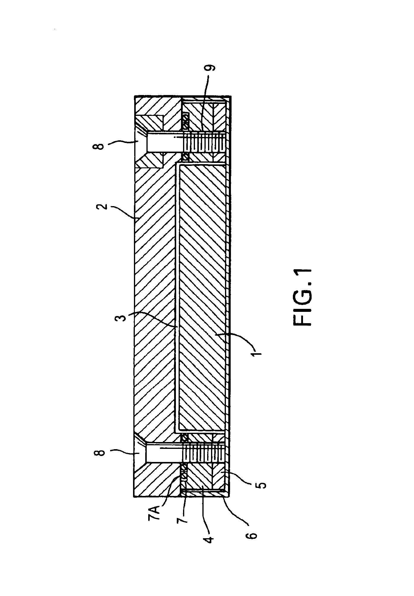
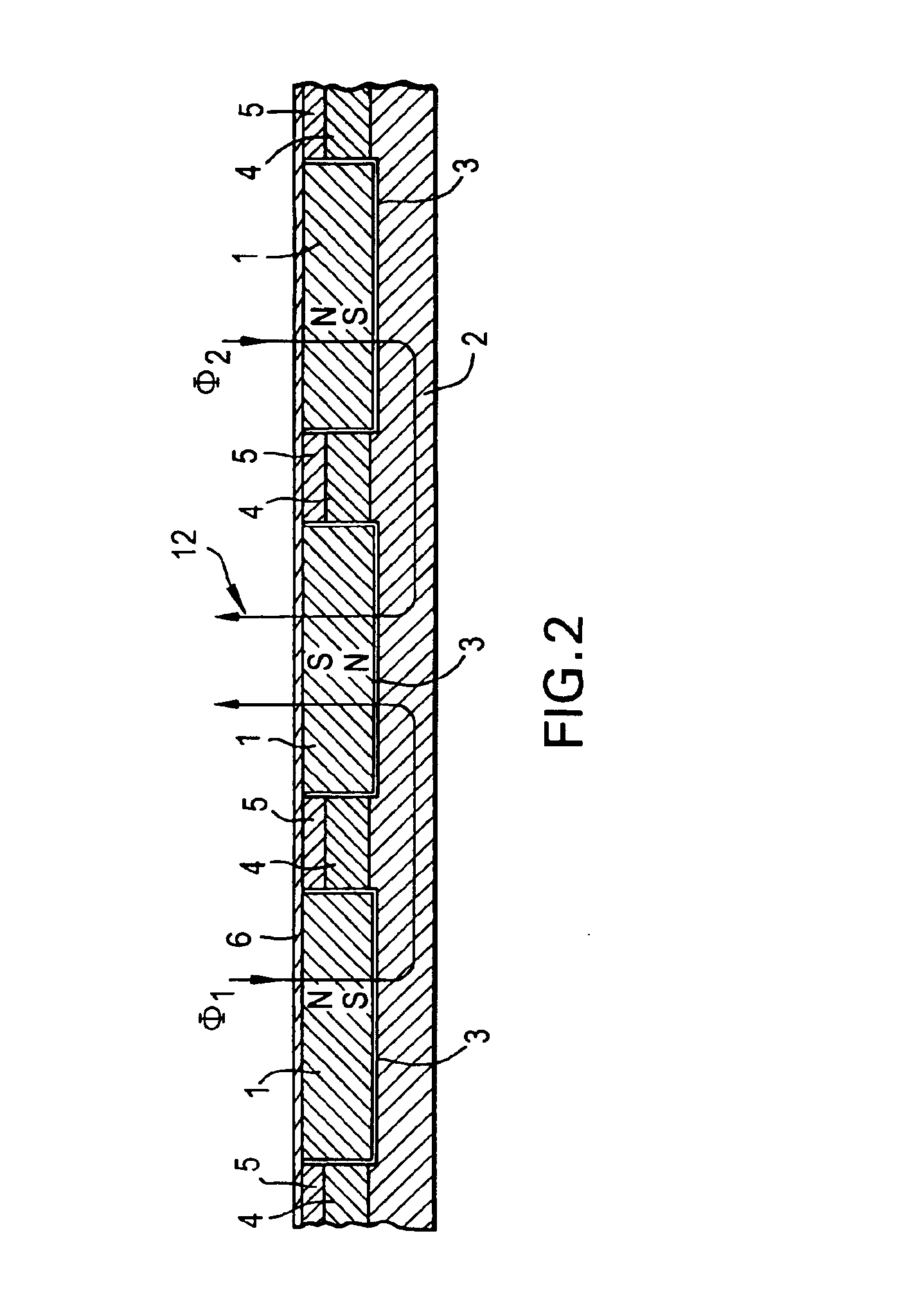
[0023]As shown in FIGS. 1-3, the device for surrounding, guiding and covering the permanent magnet array 1, comprises a frame 4, preferably made of stainless steel, which is laminated to another frame 5, preferably made of a conductive type element such as copper or aluminum or any other highly conductive material. The laminated frames 4, 5 are welded into a corrosive resistant, non-magnetic stainless steel case 6. The desired pole pitch spacing is determined by the dimensions of this double frame and cover 4, 5, 6. The frame is drilled and blind tapped 9 to accept the ferromagnetic back plate 2. The back plate 2 has a matching countersunk bolt pattern. The stainless steel portion of the frame 4 provides the surface that mates to the ferromagnetic back plate 2. This stainless steel surface 4 or the surface of the ferromagnetic back plate 2 contains an o'ring seal groove 7 precision machined around the entire perimeter and bolt holes to accept an o'ring seal 7a, preferably made of ru...


PUM


Abstract

The linear synchronous motor consists of a specific primary and secondary part. The secondary portion is a ferromagnetic back plate. An array of permanent magnets are attached to the back plate so that a fixed or variable pole pitch occurs in a precise manner between at least two magnets of alternating polarity which improves existing methods for attaching, guiding, protecting and enhancing the overall flux array produced and emitted by the permanent magnets. A one-piece electrically synchronous linear secondary stator member accompanies a primary member, the synchronous linear permanent magnet motor. The stator electrical frequency is customizeable to allow for a wide variety of braking applications.

Description

CROSS REFERENCE[0001]This utility application claims priority to U.S. Provisional Patent Application Ser. No. 60 / 383,066 filed May 24, 2002 and U.S. Provisional Patent Application Ser. No. 60 / 390,244 filed Jun. 20, 2002.FIELD OF THE INVENTION[0002]The invention relates to linear synchronous motors, and in particular to linear synchronous motors with multiple time constant circuits and an improved method of mounting permanent magnets. An embodiment provides an electrically synchronous linear secondary stator member that accompanies a primary member, the synchronous linear permanent magnet motor. An embodiment is utilized as an electro-dynamic brake for elevators as well as amusement rides such as drop towers, roller coasters and any other mobile device that requires dependable and high thrust braking applications.BACKGROUND OF THE INVENTION[0003]This invention reduces or eliminates specialized tooling to attach, guide and secure into place several permanent magnets with alternating p...

Claims


Application Information

Patent Timeline
IPC IPC(8): H02K41/03
CPCH02K41/031H02K1/276H02K2201/06H01L2924/0002H01L2924/00
Inventor MARZANO, DOMENIC P.
Owner VELOCITY MAGNETICS
Learn More