Single-stage backlight inverter and method for driving the same

a backlight inverter and single-stage technology, applied in the direction of electric variable regulation, process and machine control, instruments, etc., can solve the problems of increasing the application cost of such circuits, the control circuit is so complex, and the size reduction limitation is subject to, so as to simplify the configuration of the power switch. , to achieve the effect of reducing the stress on the power switch

Inactive Publication Date: 2005-08-16
SAMSUNG ELECTRO MECHANICS CO LTD
View PDF3 Cites 40 Cited by
  • Summary
  • Abstract
  • Description
  • Claims
  • Application Information

AI Technical Summary

Benefits of technology

[0010]Therefore, the present invention has been made in view of the above problems, and it is an object of the present invention to provide a single-stage backlight inverter and a method for driving the same, wherein switching signals to power switches for driving of a CCFL are phase-shifted to realize zero-voltage switching capable of adjusting the ratio of enable times of the power switches, thereby making it possible to reduce stresses on the power switches, readily control driving of the lamp and provide a switching control circuit in the form of an IC to simplify the configuration thereof.

Problems solved by technology

However, the above-mentioned conventional two-stage backlight inverter is disadvantageous in that complex circuits, such as the self-oscillating circuit, a buck converter, etc., are required to apply an AC voltage to the transformer device so as to drive the CCFL, resulting in an increase in application costs of such circuits.
Further, an associated control circuit is so complex that it is subject to a limitation in size reduction.
This limitation causes difficulty in building it in one IC.

Method used


Image

  • Single-stage backlight inverter and method for driving the same
  • Single-stage backlight inverter and method for driving the same
  • Single-stage backlight inverter and method for driving the same

Examples


Embodiment Construction

[0022]Now, preferred embodiments of the present invention will be described in detail with reference to the annexed drawings. In the drawings, the same or similar elements are denoted by the same reference numerals even though they are depicted in different drawings.

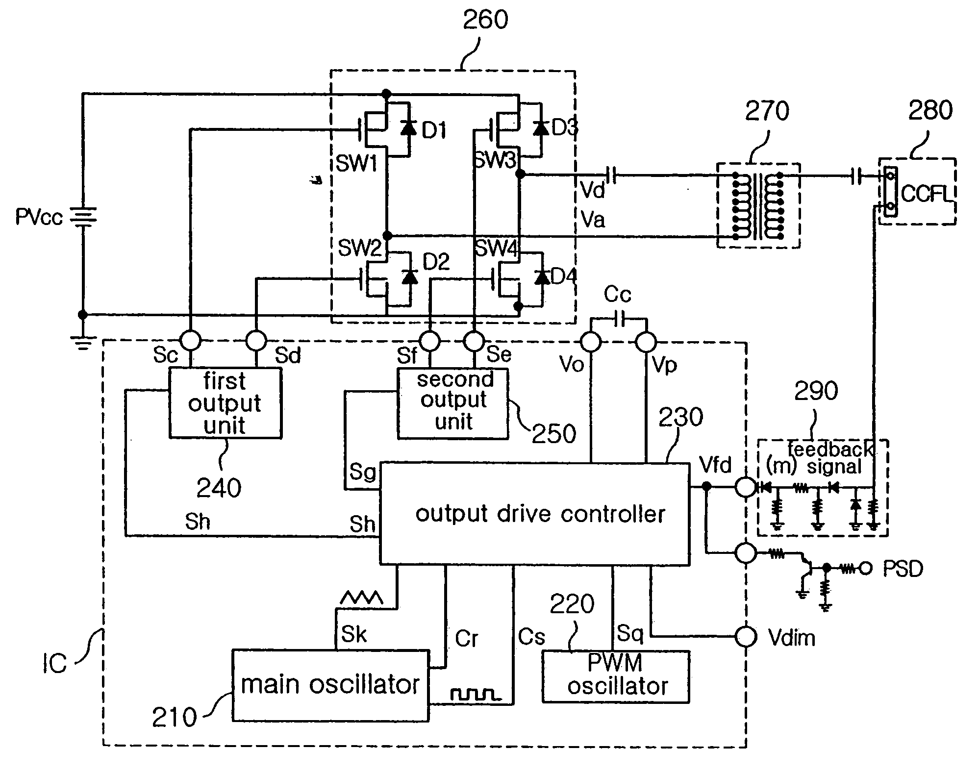
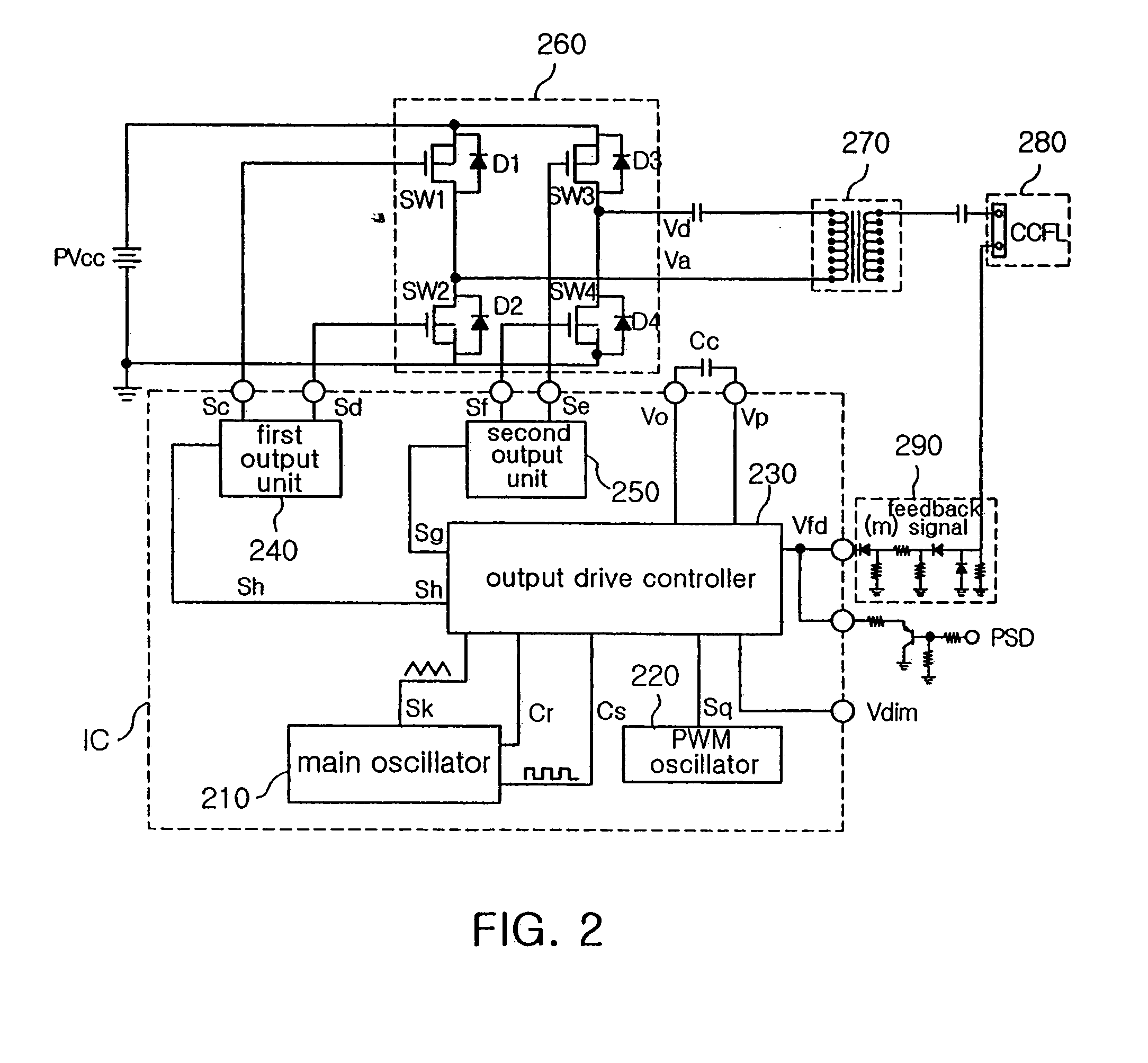
[0023]FIG. 2 is a circuit diagram showing the configuration of a single-stage backlight inverter according to the present invention.

[0024]With reference to FIG. 2, the single-stage backlight inverter according to the present invention is adapted to drive one CCFL 280 by means of one transformer 270 using a predetermined PWM oscillation signal Sq, and comprises a main oscillator 210 for generating a predetermined triangle-wave oscillation signal Sk, a predetermined clock signal Cs and an inverted clock signal Cr, and an output drive controller 230 responsive to the triangle-wave oscillation signal Sk, clock signal Cs and inverted clock signal Cr from the main oscillator 210 and first and second reference voltages Vref1 an...


PUM


Abstract

Disclosed herein are a single-stage backlight inverter and a method for driving the same. The single-stage backlight inverter comprises a main oscillator for generating a predetermined triangle-wave oscillation signal, a predetermined clock signal and an inverted clock signal, and an output drive controller responsive to the triangle-wave oscillation signal, clock signal and inverted clock signal from the main oscillator and first and second reference voltages set therein. The second reference voltage has a level set to an intermediate level of the triangle-wave oscillation signal. The output drive controller is adapted to generate a first drive control signal and generate a second drive control signal. The inverter further comprises a first output unit for outputting a pair of first switching signals in response to the first drive control signal, and a second output unit for outputting a pair of second switching signals in response to the second drive control signal.

Description

BACKGROUND OF THE INVENTION[0001]1. Field of the Invention[0002]The present invention relates to a single-stage backlight inverter for controlling driving of a cold cathode fluorescent lamp (CCFL) for a thin film transistor-liquid crystal display (TFT-LCD) panel, and more particularly to a single-stage backlight inverter and a method for driving the same, wherein switching signals to power switches for driving of a CCFL are phase-shifted to realize zero-voltage switching capable of adjusting the ratio of enable times of the power switches, thereby making it possible to reduce stresses on the power switches, readily control driving of the lamp and provide a switching control circuit in the form of an integrated circuit (IC) to simplify the configuration thereof.[0003]2. Description of the Related Art[0004]CCFLs for TFT-LCD panels are generally operated at low current, resulting in advantages such as low power consumption, low heat, high brightness and long life. In this connection, t...

Claims


Application Information

Patent Timeline
Patent Type & Authority Patents(United States)
IPC IPC(8): H02M7/5387H05B41/282H05B41/28H05B41/26
CPCH02M7/53871H05B41/2828Y02B20/186Y02B20/00H05B41/26
Inventor JEON, HYOUNG JUNMIN, BYOUNG OWNKIM, HYUN JIN
Owner SAMSUNG ELECTRO MECHANICS CO LTD
Why Eureka
Try Eureka