Dry tube fiber optic assemblies, cables, and manufacturing methods therefor

a fiber optic and assembly technology, applied in the direction of optics, fibre mechanical structures, instruments, etc., can solve the problems of thixotropic materials having drawbacks, cleaning thixotropic materials from optical waveguides, and wasting time and energy

Inactive Publication Date: 2005-08-16
CORNING OPTICAL COMM LLC
View PDF8 Cites 24 Cited by
  • Summary
  • Abstract
  • Description
  • Claims
  • Application Information

AI Technical Summary

Benefits of technology

[0004]The present invention is directed to a fiber optic dry tube assembly including at least one optical waveguide and a tube. The tube having at least a portion of the at least one optical fiber therein. The tube is formed from a bimodal polymeric material and has an average ovality of about 10 percent or less.

Problems solved by technology

On the other hand, thixotropic materials have drawbacks.
One such drawback is that they must be cleaned from the optical waveguide before connectorization of the same.
Cleaning the thixotropic material from the optical waveguide is a messy and time-consuming process.
Due to changing viscosity, the thixotropic materials can drip from an end of the tube at relatively high temperatures or the thixotropic materials may cause optical attenuation at relatively low temperatures.
Thus, cable designs have attempted to eliminate thixotropic materials from the tube, but it has been a difficult task because the thixotropic material performs many functions.
This design requires a large number of water-swellable components within the tube, which makes the design relatively expensive.
Additionally, with the elimination of the thixotropic material the tube is likely to deform or collapse before cooling.
This deformation of the tube is not addressed by the patent and can cause numerous problems.
Problems caused by tube deformation include increased optical attenuation, decreased tube crush strength, kinking of the tube, non-uniform jacket thickness over the tube, larger cable diameters, and difficulties in stranding the tube about a central member.

Method used


Image

  • Dry tube fiber optic assemblies, cables, and manufacturing methods therefor
  • Dry tube fiber optic assemblies, cables, and manufacturing methods therefor
  • Dry tube fiber optic assemblies, cables, and manufacturing methods therefor

Examples


Embodiment Construction

[0015]The present invention will now be described more fully hereinafter with reference to the accompanying drawings showing preferred embodiments of the invention. The invention may, however, be embodied in many different forms and should not be construed as limited to the embodiments set forth herein; rather, these embodiments are provided so that the disclosure will fully convey the scope of the invention to those skilled in the art. The drawings are not necessarily drawn to scale but are configured to clearly illustrate the invention.

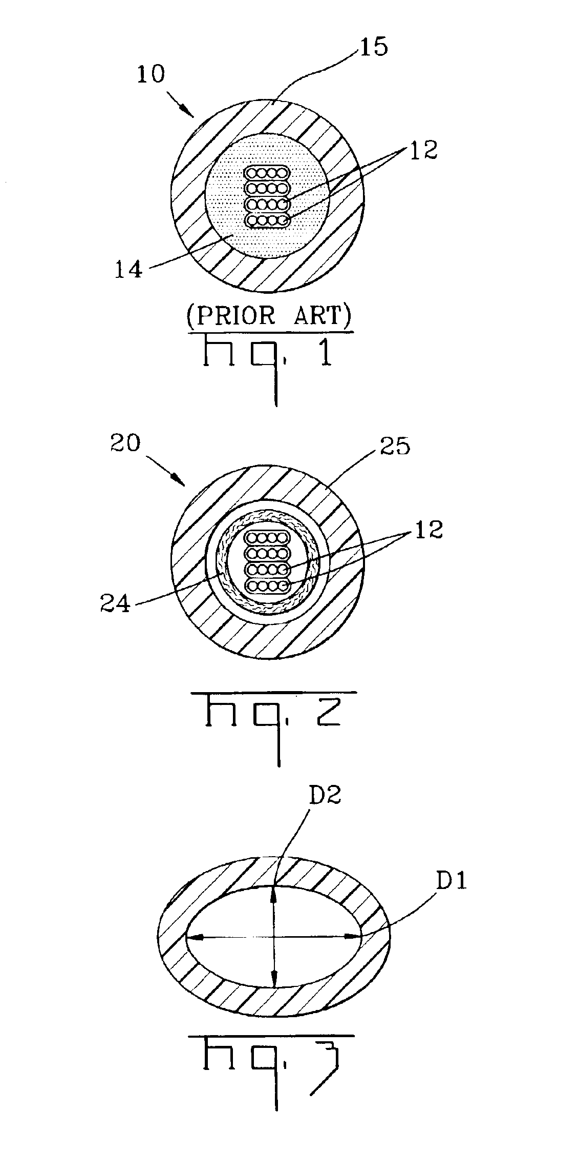
[0016]FIG. 2 depicts a fiber optic dry tube assembly 20 according to the present invention having at least one optical waveguide 12 and a water-swellable material 24 disposed within a tube 25. Tube 25 is formed from a bimodal polymeric material. Bimodal polymeric materials of the present invention include materials having at least a first polymer material having a relatively high molecular weight and a second polymer material having a relatively low...


PUM

PropertyMeasurementUnit
melt strengthaaaaaaaaaa
molecular weight distributionaaaaaaaaaa

Abstract

A fiber optic dry tube assembly and a method of manufacturing the same includes at least one optical waveguide and a tube. The tube houses at least a portion of the at least one optical fiber and is formed from a bimodal polymeric material. The tube has an average ovality of about 10 percent or less. In other embodiments, the bimodal polymeric material that forms the tube has a melt index of about 1.0 g/10 minutes or less, a melt strength in the range of about 8 cN to about 35 cN at 190° C,. and/or a polydisperity of about 7 or greater. Additionally, the dry tube assemblies of the present invention can form a portion of a cable.

Description

FIELD OF THE INVENTION[0001]The present invention relates to dry tube fiber optic assemblies, cables, and manufacturing methods therefore. More specifically, the invention relates to dry tube fiber optic assemblies and cables having a tube formed from a bimodal polymeric material with a predetermined ovality and manufacturing methods therefor.BACKGROUND OF THE INVENTION[0002]Fiber optic tube assemblies and cables include optical waveguides such as optical fibers that transmit optical signals such as voice, video, and / or data information. Depicted in FIG. 1 is a conventional fiber optic tube assembly 10. Conventional tube assembly 10 includes a plurality optical waveguides 12 in a ribbon format that are disposed within a tube 15 filled with a thixotropic material 14 such as grease. Filling tube 15 with thixotropic material 14 serves several functions. For instance, thixotropic material 14 allows for movement between the optical waveguides and the tube, cushioning of the optical waveg...

Claims


Application Information

Patent Timeline
Patent Type & Authority Patents(United States)
IPC IPC(8): G02B6/44
CPCG02B6/443G02B6/4433G02B6/4494G02B6/4403G02B6/44384
Inventor TEDDER, CATHARINA L.GREENWOOD, JODY L.TEMPLE, JR., KENNETH D.
Owner CORNING OPTICAL COMM LLC
Why Eureka
Try Eureka