Multiple mode power throttle mechanism

a power throttle mechanism and multi-mode technology, applied in the field of microprocessors, can solve the problems of large power dissipation problems, processors to dissipate large amounts of power, and smart compilers and out of order execution can only extract so much instruction level parallelism (ilp) from most cod

Inactive Publication Date: 2005-08-16
INTEL CORP
View PDF43 Cites 65 Cited by
  • Summary
  • Abstract
  • Description
  • Claims
  • Application Information

AI Technical Summary

Problems solved by technology

When fully engaged by an executing program, these resources can create significant power dissipation problems.
Smart compilers and out of order execution can only extract so much instruction level parallelism (ILP) from most code.
Hobbling the processor in this manner leaves a thermal margin for those code sequences that cause the processor to dissipate l

Method used


Image

  • Multiple mode power throttle mechanism
  • Multiple mode power throttle mechanism
  • Multiple mode power throttle mechanism

Examples


Embodiment Construction

[0021]The following discussion sets forth numerous specific details to provide a thorough understanding of the invention. However, those of ordinary skill in the art, having the benefit of this disclosure, will appreciate that the invention may be practiced without these specific details. In addition, various well-known methods, procedures, components, and circuits have not been described in detail in order to focus attention on the features of the present invention.

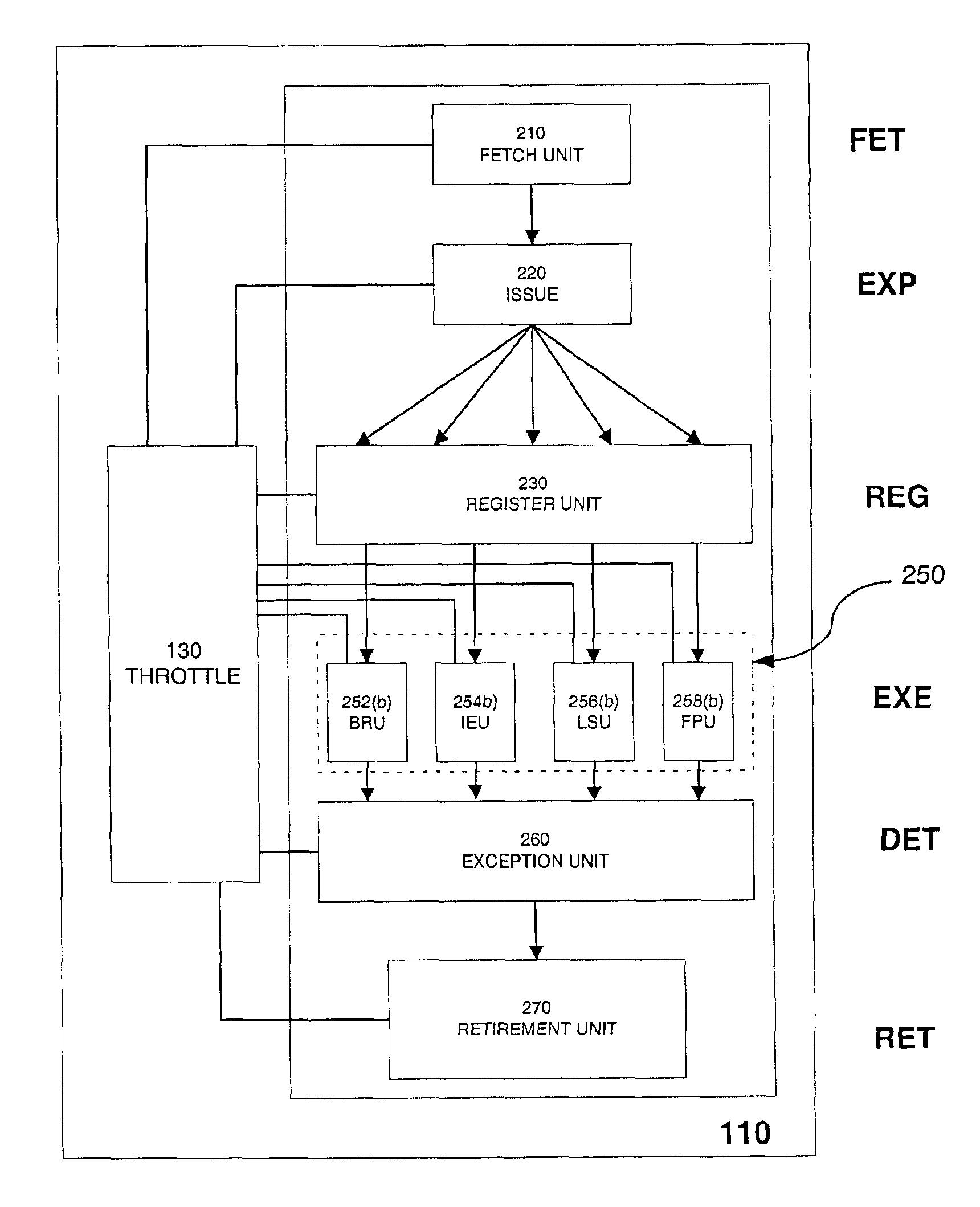
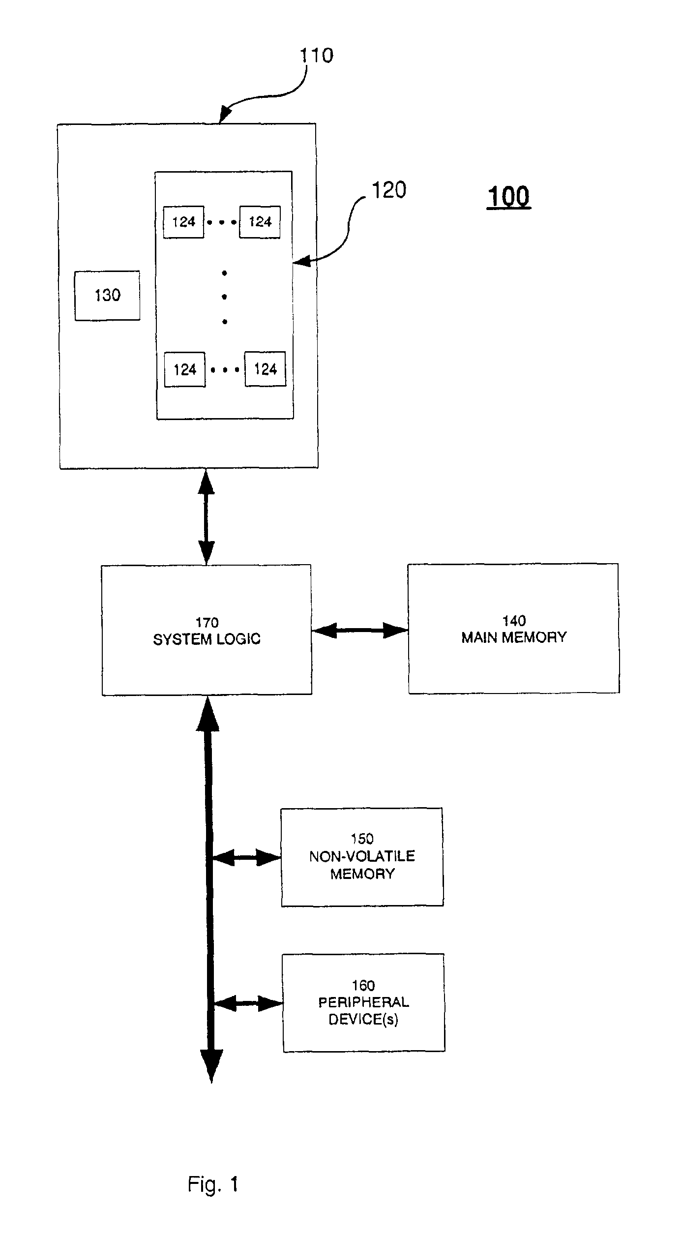
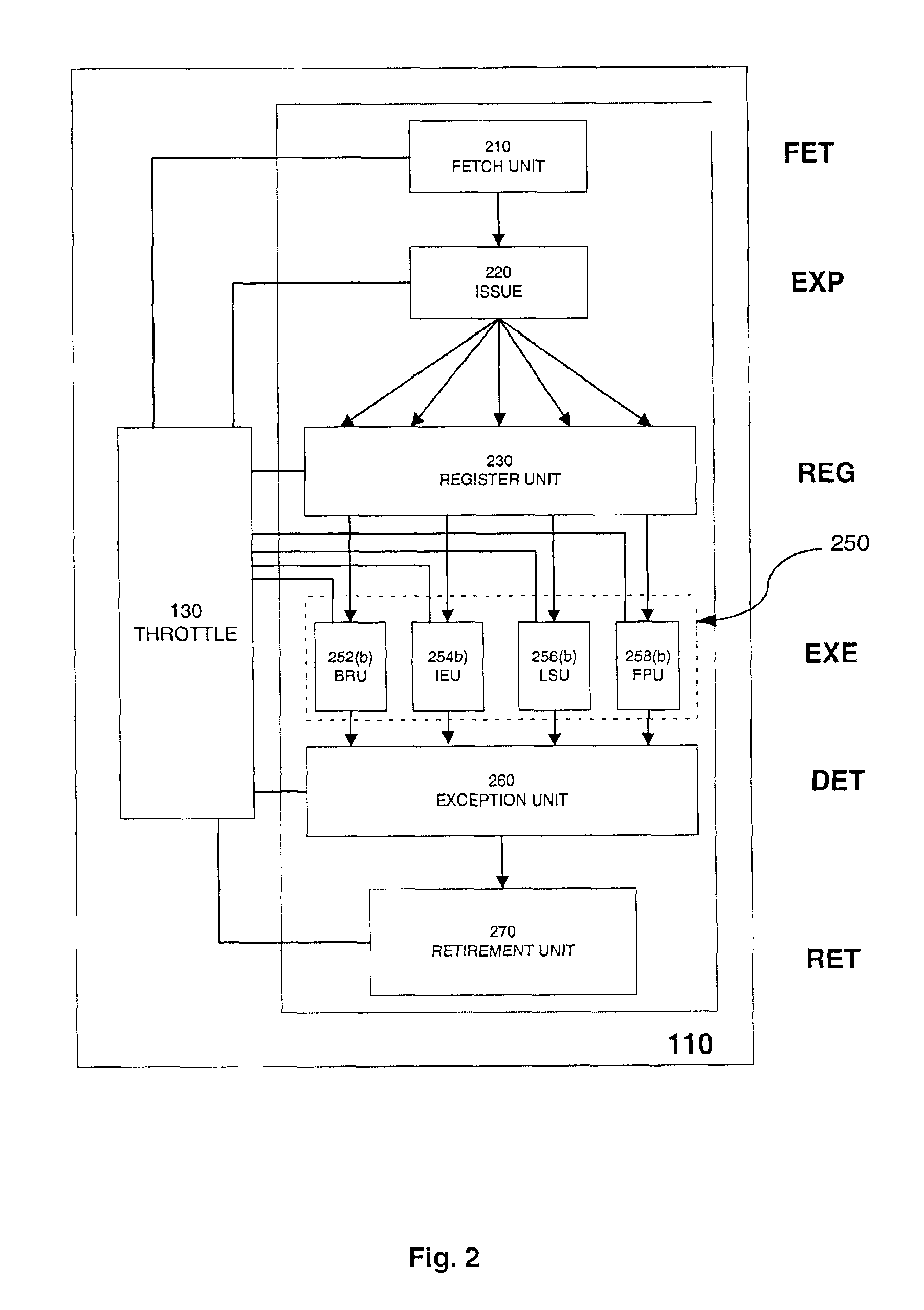
[0022]The present invention provides a mechanism for controlling the power dissipation of a processor using multiple power control modes. A computer system includes a processor having a digital throttle. The digital throttle monitors the activity of the processor to estimate the processor's power state. The digital throttle triggers one of the multiple power control modes, if warranted by the estimated power state. For one embodiment of the invention, a first power mode is triggered, if the estimated power state reaches ...


PUM


Abstract

A processor includes a digital throttle to monitor the activity of various units of the processor's instruction execution pipeline, and to determine a power state for the processor from the monitored activity. One of two or more power control mechanisms is engaged, responsive to the power state of the processor reaching a threshold.

Description

RELATED PATENT APPLICATIONS[0001]This patent application is related to U.S. patent application Ser. No. 10 / 041,092, “Digital Throttle for Multiple Operating Points”, filed on even date herewith and assigned to the same assignee.BACKGROUND OF THE INVENTION[0002]1. Technical Field[0003]The present invention relates to microprocessors and, in particular, to mechanisms for controlling power consumption in microprocessors.[0004]2. Background Art[0005]Modern processors include extensive execution resources to support concurrent processing of multiple instructions. A processor typically includes one or more integer, floating point, branch, and memory execution units to implement integer, floating point, branch, and load / store instructions, respectively. Register files and on-chip caches are also provided to supply the execution resources with operands. When fully engaged by an executing program, these resources can create significant power dissipation problems.[0006]Instruction code sequen...

Claims


Application Information

Patent Timeline
IPC IPC(8): G06F1/32G06F9/318
CPCG06F1/3203G06F1/3243G06F9/3017G06F9/3836G06F9/3873G06F9/3857G06F9/384G06F9/3869Y02B60/1217Y02B60/1239Y02D10/00G06F9/3858
Inventor BURNS, JAMES S.RUSU, STEFANAYERS, DAVID J.GROCHOWSKI, EDWARD T.ENG, MARSHATIWARI, VIVEK
Owner INTEL CORP
Why Eureka
Try Eureka