Gun rest

Inactive Publication Date: 2005-08-23
COYOTE JAKES
View PDF13 Cites 62 Cited by
  • Summary
  • Abstract
  • Description
  • Claims
  • Application Information

AI Technical Summary

Problems solved by technology

More particularly, the gun rest could not be adjusted by the user while holding the firearm.
There has been no practical gun

Method used


Image

  • Gun rest
  • Gun rest

Examples


Embodiment Construction

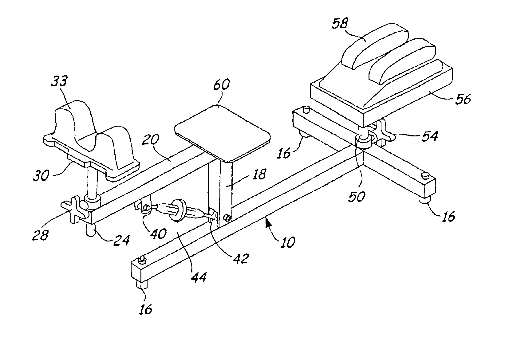
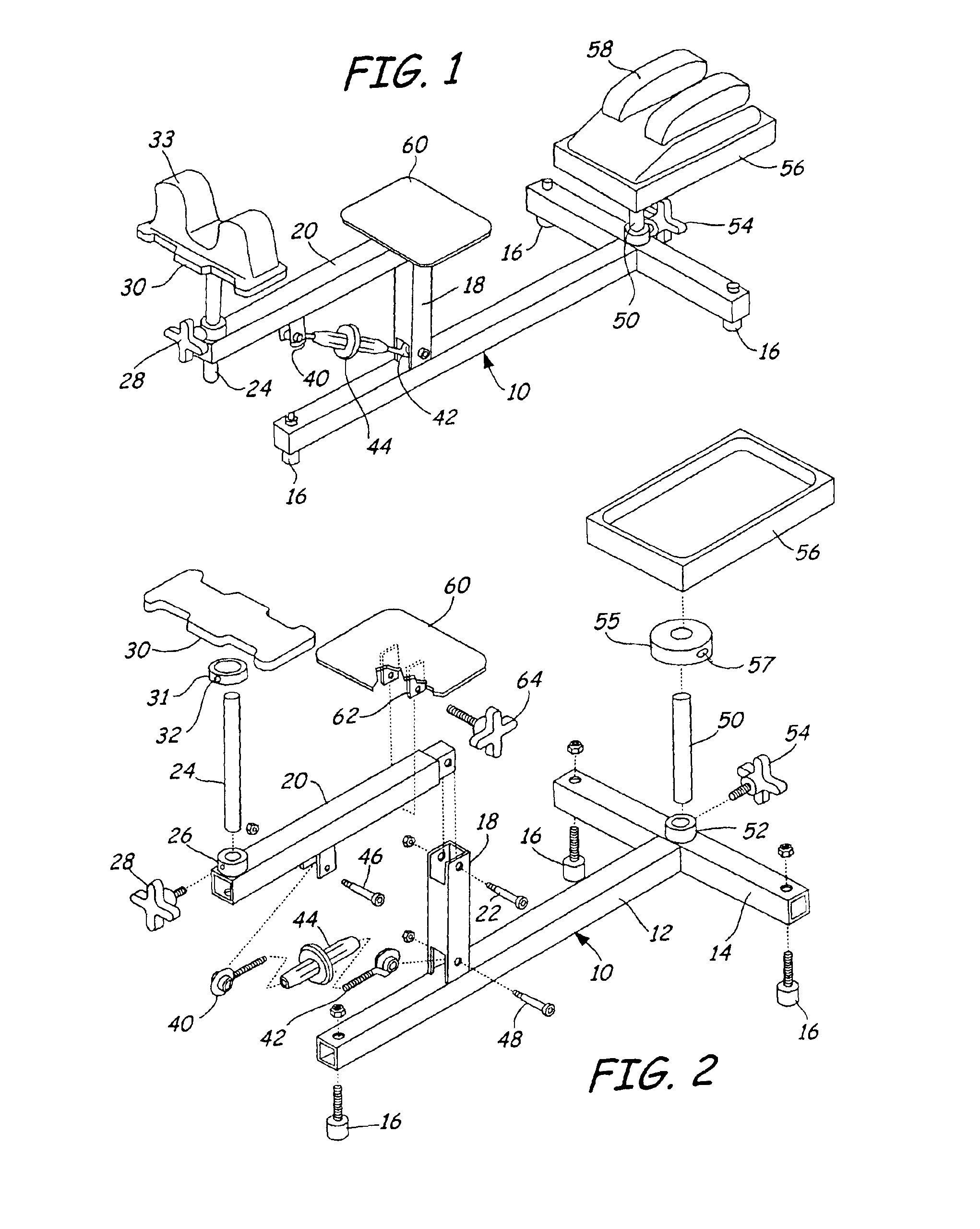
[0012]FIGS. 1 and 2 illustrate a gun rest in accordance with an embodiment of the present invention. The gun rest has a T-shaped steel base member 10 having long member 12 and a rear cross-member 14. Feet 16 are threadably fastened to the forward end of member 12 and to each end of cross-member 14, and are arranged to engage a rigid support plane, such as the ground or a table top.

[0013]A vertical support member 18 is attached to member 12, such as by welding, and support arm 20 is pivotally mounted by pivot pin 22 to an upper end of support member 18. Tubular support member 24 is slidably received in receiver 26 of arm 20 so that member 24 is substantially normal or perpendicular to arm 20. Member 24 is locked to a selected elevation by fastener 28, threadably engaged to receiver 26 to bear against support 24. Conveniently, fastener 28 includes a knob to permit turning the fastener by hand. Thus, the position of member 24 relative to member to is fixed by frictional engagement of f...


PUM


Abstract

A gun rest has a first support mounted to a base and a support arm pivotally mounted to the first support. A platform for supporting a firearm barrel is mounted to the support arm. A manually-operable adjustment assembly couples the first support to the support arm to fixedly adjust an angular position of the platform relative to the base. The adjustment assembly has first and second fasteners pivotally mounted to the first support and to the support arm, and a manually-operable coupler threaded to the fasteners to selectively alter a distance between the first and second fasteners. A second platform mounted to the base supports a firearm stock, and an optional third platform is removably attachable to the support arm to support a pistol grip and hand of a user.

Description

CROSS-REFERENCE TO RELATED APPLICATIONS[0001]This application claims benefit of U.S. Provisional Application No. 60 / 384,516 filed May 29, 2002 for “Gun Rest” by Gary L. Krien.FIELD OF THE INVENTION[0002]This invention relates to adjustable gun rests, and particularly to gun rests supporting an elevation of a forward part of the firearm, such as the barrel, for adjusting the orientation of the muzzle of the firearm.BACKGROUND OF THE INVENTION[0003]Gun rests are used to support firearms in a fixed position during target practice and competitions, as well as to adjust sights, including telescopic sights, of the firearm. Typically, gun rests include resilient bags, such as a plastic bag filled with a moldable or pliable material like sand. The bag conforms to the shape of the barrel of the firearm to hold the barrel in a fixed position. A second bag, also filled with moldable material, is used with rifles to hold the stock of the firearm in a fixed position.[0004]One important considera...

Claims


Application Information

Patent Timeline
IPC IPC(8): F41A23/00F41A23/02
CPCF41A23/02
Inventor KRIEN, GARY L.
Owner COYOTE JAKES
Why Eureka
Try Eureka