Neutron reflection spectrometer optical path structure capable of performing rapid switching between polarization mode and non-polarization mode

A non-polarization and reflection spectrum technology, which is applied in material analysis using neutrons, material analysis using wave/particle radiation, instruments, etc. Problems such as polarization neutron reflection experiment, failure to realize sample and detector linkage, etc., to achieve the effect of simple realization

Active Publication Date: 2017-09-15
DONGGUAN NEUTRON SCI CENT
View PDF6 Cites 7 Cited by
  • Summary
  • Abstract
  • Description
  • Claims
  • Application Information

AI Technical Summary

Problems solved by technology

[0007] The inventor of the patent of the present invention disclosed a neutron can be used for neutron The structural design of the air bearing rotating platform of the reflectance spectrometer, the paper mainly discloses the structural design of the air bearing rotating platform and after theoretical analysis and data processing test methods, it is concluded that the structure of the air bearing plus friction wheel drive can meet the requirements of multifunctional reflectance spectroscopy. The movement requirements of the reflection arm of the instrument, although the air bearing rotating platform disclosed in this document can be applied to the movement and positioning of the detector of the neutron reflectance spectrometer, but it cannot realize the linkage between the sample and the detector, that is, in the technical inspiration of this document Under this condition, the optical path structure of the neutron reflectance spectrometer that can quickly switch between polarized and non-polarized modes is not available; in addition, the patent number is 201310081905.1, and the patent name is a precision body movement for high-resolution neutron powder diffraction spectrometer In the patent literature of the device, it is disclosed that the detector carrying unit is supported by air flotation, the friction wheel is driven by the driving motor to drive the detector carrying unit to rotate around the sample center, and the detector carrying unit is fed back through the circular grating set in the center. Rotation angle and positioning accuracy, the air-supported detector carrier unit can also be applied to the movement and positioning of the detector of the neutron reflectance spectrometer, but it is still impossible to realize the linkage between the sample and the detector, that is, under the technical inspiration of this document , it is impossible to obtain the optical path structure of the neutron reflectance spectrometer that can quickly switch between polarized and non-polarized modes
[0008] Another patent number is 201110091018.3, and the patent name is the patent document of the adjustment structure of the neutron optical path of the horizontal sample geometric neutron reflectance spectrometer, which discloses an incident lifting mechanism and a reflection lifting mechanism applied to the neutron reflectance spectrometer. By adjusting the position of the slit and the neutron flight tube, the linkage between the sample and the detector is realized, but its essence is to change the incident angle and reflection angle of the neutron beam at the same time, so as to satisfy the geometric relationship of reflection, which cannot be applied to flight The collimation adjustment of the flight distance of the time spectrometer, and only the non-polarized neutron reflection experiment of horizontally placed samples can be performed on this spectrometer, and the polarized neutron reflection experiment cannot be performed. Under the technical inspiration of this document, The optical path structure of the neutron reflectance spectrometer that can quickly switch between polarized and non-polarized modes is also not available

Method used


Image

  • Neutron reflection spectrometer optical path structure capable of performing rapid switching between polarization mode and non-polarization mode
  • Neutron reflection spectrometer optical path structure capable of performing rapid switching between polarization mode and non-polarization mode
  • Neutron reflection spectrometer optical path structure capable of performing rapid switching between polarization mode and non-polarization mode

Examples


specific Embodiment approach

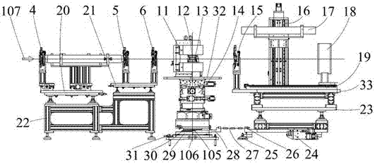
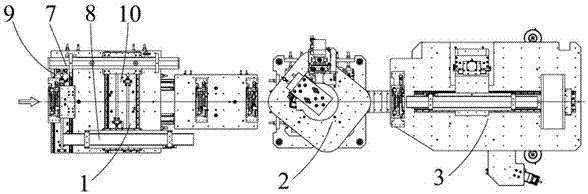
[0046] Such as Figure 1-15 As shown, a neutron reflectance spectrometer optical path structure that can quickly switch between polarized and non-polarized modes, the optical path structure mainly includes incident arms 1, Sample stage 2 and reflection arm 3.

[0047] The incident arm 1 includes a first slit 4, a second slit 5, a third slit 6, a focusing conduit 7, a polarizer 8, a first translation stage 9, a second translation stage 10, a first platform 20, The second platform 21 and the incident arm base 22; wherein the incident arm base 22 is placed on the precision granite ground, and the first platform 20 is fixedly installed on the incident end of the incident arm base 22 along the incident neutron beam direction, the first The second platform 21 is fixedly installed on the exit end of the incident arm base 22 along the direction of the incident neutron beam, and the first translation platform 9 is fixedly installed on the incident end of the first platform 20 along th...

Embodiment 1

[0057] Embodiment 1: Utilize the present invention to carry out common non-polarization mode experiment

[0058] Such as Figure 16 As shown, a neutron optical path structure for a neutron reflectance spectrometer, the optical path structure mainly includes an incident arm 1, a sample stage 2 and a reflective arm that are sequentially placed on the precision granite ground along the direction of the incident neutron beam 3. The incident arm 1 mainly includes a first slit 4, a second slit 5, a third slit 6, a focusing conduit 7, a polarizer 8, a first translation stage 9, a second translation stage 10, a first Platform 20, second platform 21, and incident arm base 22; the sample stage 2 mainly includes a vertical electromagnet 11, a sample 12, a cryostat 13, a third platform 32, a sample attitude adjustment mechanism 14, and a sample stage base 31; The reflective arm 3 mainly includes a fourth slit 15, a lifting platform 16, a polarization analyzer 17, a detector 18, a third t...

Embodiment 2

[0059] Embodiment 2: Using the present invention to carry out high-throughput non-polarization mode experiments

[0060] Such as Figure 17 As shown, a neutron optical path structure for a neutron reflectance spectrometer, the optical path structure mainly includes an incident arm 1, a sample stage 2 and a reflective arm that are sequentially placed on the precision granite ground along the direction of the incident neutron beam 3. The incident arm 1 mainly includes a first slit 4, a second slit 5, a third slit 6, a focusing conduit 7, a polarizer 8, a first translation stage 9, a second translation stage 10, a first Platform 20, second platform 21, and incident arm base 22; the sample stage 2 mainly includes a vertical electromagnet 11, a sample 12, a cryostat 13, a third platform 32, a sample attitude adjustment mechanism 14, and a sample stage base 31; The reflective arm 3 mainly includes a fourth slit 15, a lifting platform 16, a polarization analyzer 17, a detector 18, a t...


PUM


Abstract

The present invention relates to the technical field of neutron reflection, particularly to a neutron reflection spectrometer optical path structure capable of performing rapid switching between a polarization mode and a non-polarization mode. The optical path structure mainly comprises an incident arm, a sample table and a reflection arm, wherein the incident arm comprises a first slit, a second slit, a third slit, a focusing conduction pipe, a polarizer, a first translation table, a second translation table, a first platform, a second platform and an incident arm base, the sample table comprises a vertical electromagnet, a sample, a cryostat, a third platform, a sample attitude adjustment mechanism and a sample table base, and the reflection arm comprises a fourth slit, a lifting table, a polarization analyzer, a detector, a third translation table, a reflection arm base, a fourth platform and a reflection arm rotation drive mechanism. According to the present invention, the rapid switching between the polarization mode and the non-polarization mode can be achieved by simply controlling and adjusting the movements of the three translation tables and the lifting table, such that the structure is easily achieved, and the precision of the experiment is high.

Description

technical field [0001] The invention relates to the technical field of neutron reflection, in particular to an optical path structure of a neutron reflection spectrometer capable of rapidly switching polarization and non-polarization modes. Background technique [0002] Neutron reflection technology is an advanced material characterization technology that obtains information such as the structural composition of the interface in the range of 0.5-500nm by measuring the reflection of neutrons by the interface thin film material. The unique properties such as electrification make neutron reflection technology increasingly become an important research method for the film structure of thin film materials; The interaction between neutrons and the magnetic moments of magnetic materials can be recorded by the reflected neutrons, making the neutron reflection technique a powerful tool for obtaining the magnetic structure information of these magnetic thin film materials and measuring...

Claims


Application Information

Patent Timeline
Patent Type & Authority Applications(China)
IPC IPC(8): G01N23/20
CPCG01N23/005G01N23/20008G01N23/20083G01N2223/03G01N2223/045G01N2223/052G01N2223/106G01N2223/30
Inventor 肖松文孙远吴延岩朱涛
Owner DONGGUAN NEUTRON SCI CENT
Why Eureka
Try Eureka