Bridging device for joint gaps

a bridging device and joint technology, applied in bridges, single-unit pavings, bridges, etc., can solve the problems of displacement of building parts, said bridging device or expansion joint construction, respectively, is no longer suitable for intended use, etc., and achieves the effect of stabilizing the bridging devi

Inactive Publication Date: 2005-08-23
FRIEDRICK MAURER SOHNE GMBH & CO KG
View PDF11 Cites 11 Cited by
  • Summary
  • Abstract
  • Description
  • Claims
  • Application Information

AI Technical Summary

Benefits of technology

[0006]It is, therefore, the main object of the present invention to create a bridging device avoiding these drawbacks of the known bridging devices and to make available a bridging device in particular, which permits securing said expansion joint construction or edge construction at the joint gap against destruction in case of given movement limits of the bordering building parts being exceeded with maintenance of the intended use, wherein various differing movements and limit exceedings are to be secured.

Problems solved by technology

In spite of the fact that the bridging device disclosed in EP 0 821 104 reliably meets this demand, it nevertheless includes the disadvantage that said bridging device or expansion joint construction, respectively, is no longer suitable for the intended use after the safety means having been actuated, since the expansion joint construction in case of excessive reduction of the width of said joint gap, e.g. by an earthquake, presses the expansion joint construction out of the joint gap.
Moreover, said safety means does not permit compensation of other excessive movements exceeding a standard value, of the buildings creating said joint gap, with respect to one another, an enlargement of said joint gap width e.g., exceeding the admissible magnitude or a transversal movement of the building parts with respect to one another, which causes a displacement of the building parts with respect to the joint gap.

Method used


Image

  • Bridging device for joint gaps
  • Bridging device for joint gaps
  • Bridging device for joint gaps

Examples


Embodiment Construction

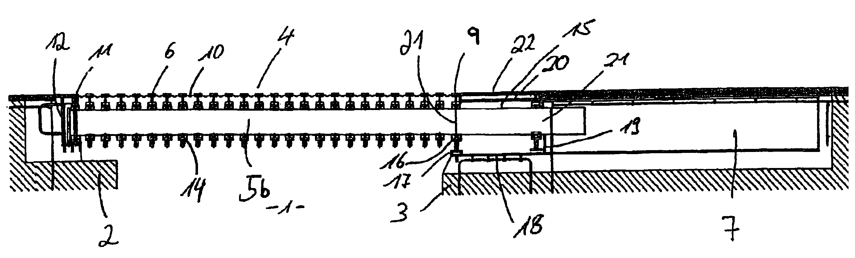
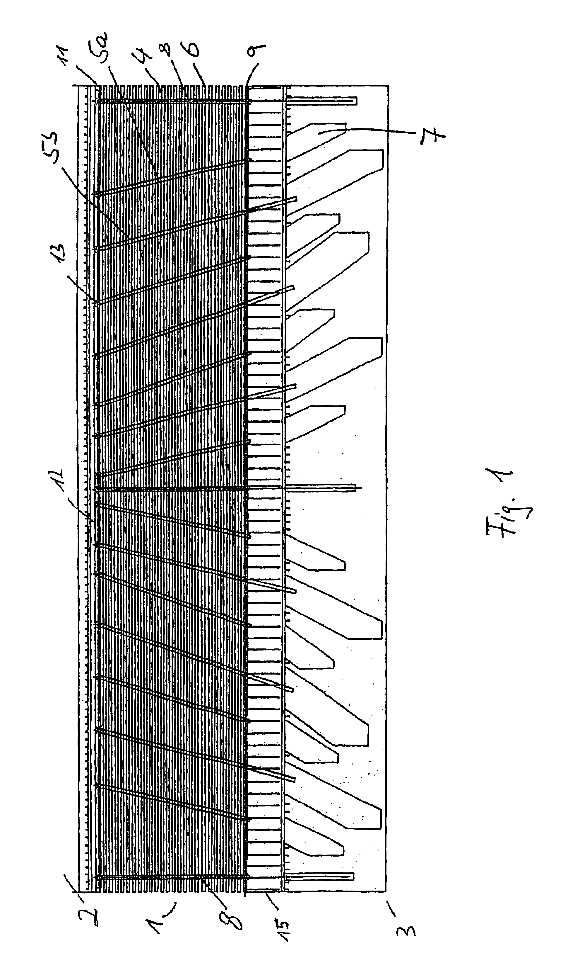
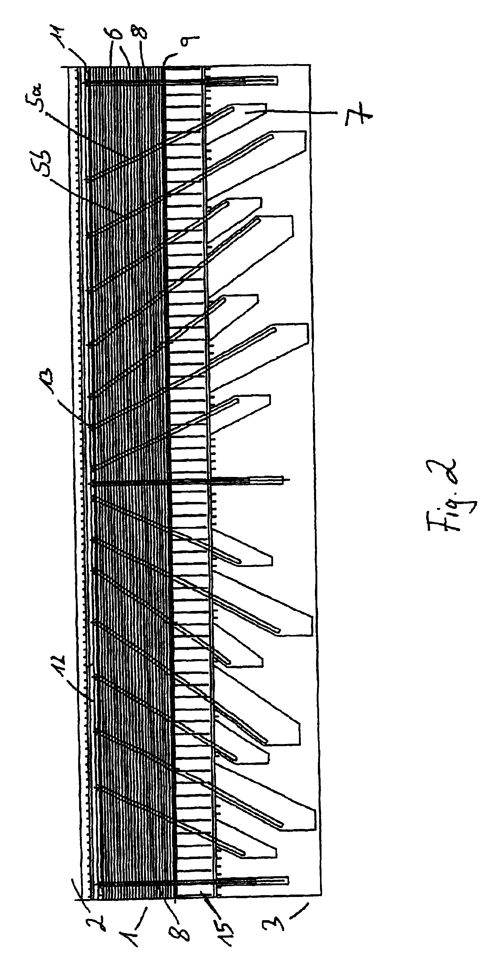
[0038]FIG. 1 shows the bridging device in accordance with the present invention, bridging a joint gap 1 between building parts 2 and 3. Herein, building part 2 e.g. is the stationary bridge head and building part 3 represents the movable bridge construction element. The bridging device in accordance with the present invention, shown in FIG. 1, comprises an expansion joint construction 4 essentially consisting of the roadway crossheads 5a, 5b and the edge crossheads 8 as well as the central profiles 6 arranged thereon.

[0039]Said crossheads 5a, 5b and 8 with their ends bear on building parts 2 and 3. On the bridge-head side ends said crossheads 5a, 5b and 8 are firmly received in crosshead connections 13, crossheads 5a and 5b being pivotably arranged around crosshead connections 13. The other end of crossheads 5a, 5b an 8 is freely movably received in crosshead boxes 7 which are arranged in the bridge construction element 3 below the bridge deck, e.g. the roadway.

[0040]On the building...


PUM


Abstract

A bridging device for joint gaps (1) between building parts (2, 3) including bridge parts, with an expansion joint construction (4) bridging a joint gap (1). The expansion joint construction (4) permits position changes of the building parts (2, 3) with respect to one another. A safety construction (12, 15) is provided which permits a position change of the building parts (2, 3) with respect to one another without a separation destroying the function of the bridging device. The safety construction (12, 15) comprises at least two mutually firmly connected elements which upon exceeding of a defined threshold load are separated and movable with respect to one another. One element is firmly arranged on one of the building parts (2, 3) and the other element is part of the expansion joint construction (4) or receives the latter. The two connected element are defined by a rail (24)and a slide (25). The slide (24) is displaceable in the rail (25) in order to balance shifting movements including transversal movements between bridge parts.

Description

BACKGROUND OF THE INVENTION[0001]1. Field of the Invention[0002]The present invention relates to a bridging device for joint gaps between building parts including a safety construction which prevents a separation of the building parts from destroying the brigiding device.[0003]2. Description of the Related Art[0004]In buildings exceeding certain dimensions it is necessary to provide for expansion joints for compensating thermal expansion in order to avoid destruction of the building. This is particularly true for bridge constructions in which thermal expansions can assume enormous dimensions. Therefore, it is known, for bridge constructions in particular, to provide for corresponding bridging devices for joint gaps between building parts, bridge parts in particular. European EP 0 821 104 e.g. discloses such bridging device. Said bridging device disclosed in EP 0 821 104 comprises a safety means which in addition to the compensation of standard dimension alterations permits protectio...

Claims


Application Information

Patent Timeline
Patent Type & Authority Patents(United States)
IPC IPC(8): E01D19/06E01D19/00E01C11/02E01D2/00E01D18/00E01C5/00E04B1/62
CPCE01D19/062
Inventor BRAUN, CHRISTIAN
Owner FRIEDRICK MAURER SOHNE GMBH & CO KG
Why Eureka
Try Eureka