Combustor containing fuel nozzle

a combustor and fuel nozzle technology, which is applied in the direction of machines/engines, combustion types, lighting and heating apparatus, etc., can solve the problems of difficult to produce pre-mixed air uniformly mixed, difficult to inject fuel through the injection port, and difficulty in producing pre-mixed air, etc., to achieve the effect of reducing nox, preventing the occurrence of vortex, and reducing the occurrence of nox

Inactive Publication Date: 2005-08-23
MITSUBISHI HEAVY IND LTD
View PDF16 Cites 19 Cited by
  • Summary
  • Abstract
  • Description
  • Claims
  • Application Information

AI Technical Summary

Benefits of technology

[0016]Namely, according to the other embodiment of the present invention, the occurrence of the vortex can be relatively easily prevented without providing the projection. Accordingly, the occurrence of NOx can be reduced because the uniformly mixed pre-mixed air can be produced. A combustion vibration can be prevented because the flow coefficient can be stabilized. Also, the combustor containing such a fuel nozzle can be easily manufactured at a low cost.

Problems solved by technology

Therefore, it is difficult to inject fuel through the injection port 260a.
There is a possibility that a combustion vibration may occur because uniform pre-mixed air is not produced due to scattering of a flow coefficient.
Accordingly, it is difficult to produce pre-mixed air that is uniformly mixed.

Method used


Image

  • Combustor containing fuel nozzle
  • Combustor containing fuel nozzle
  • Combustor containing fuel nozzle

Examples


Embodiment Construction

[0029]Embodiments of the present invention will be described below with reference to the accompanying drawings. In the following drawings, similar members are designated by the same reference numerals. The scale of these drawings is changed as necessary for easy understanding.

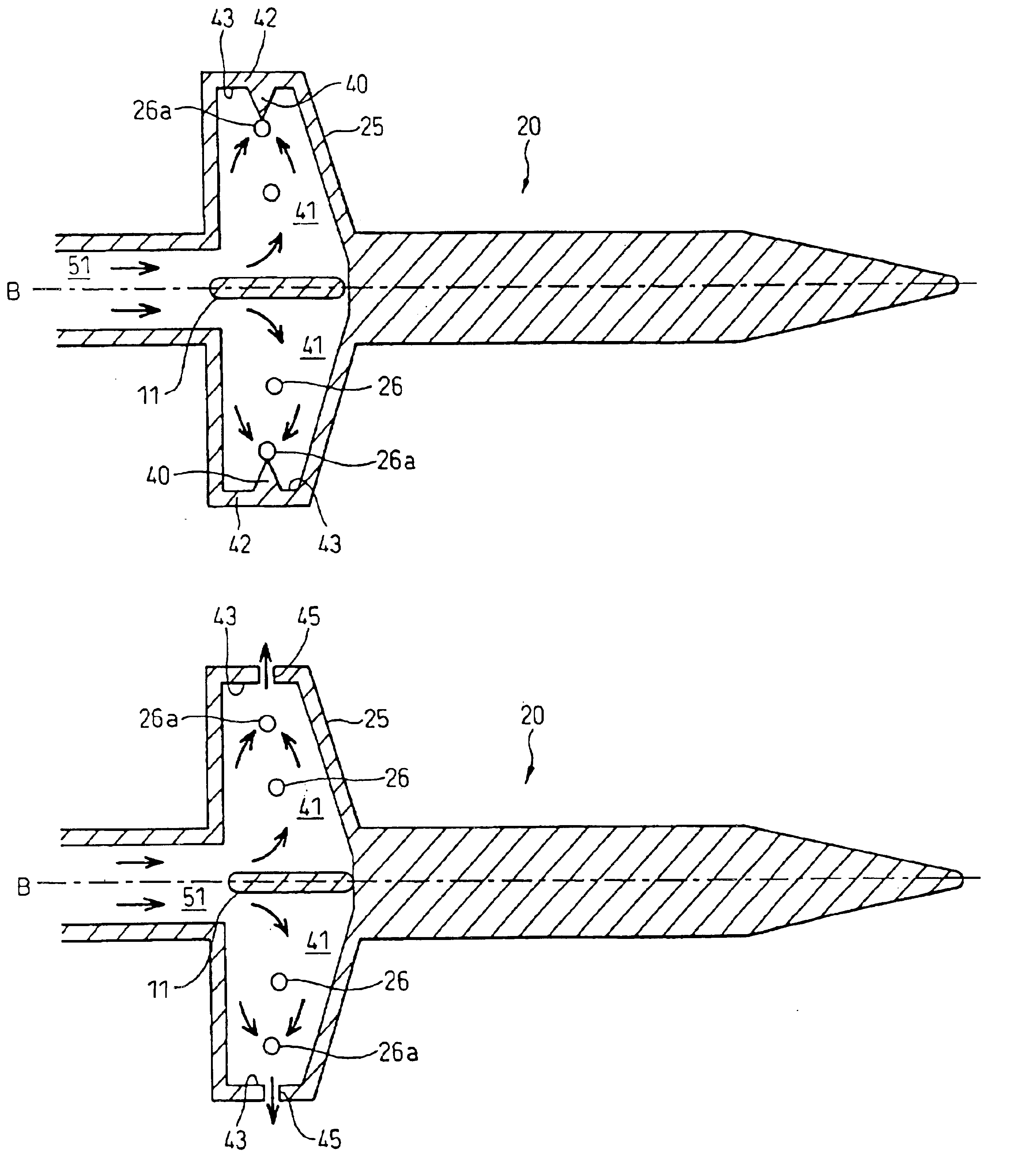
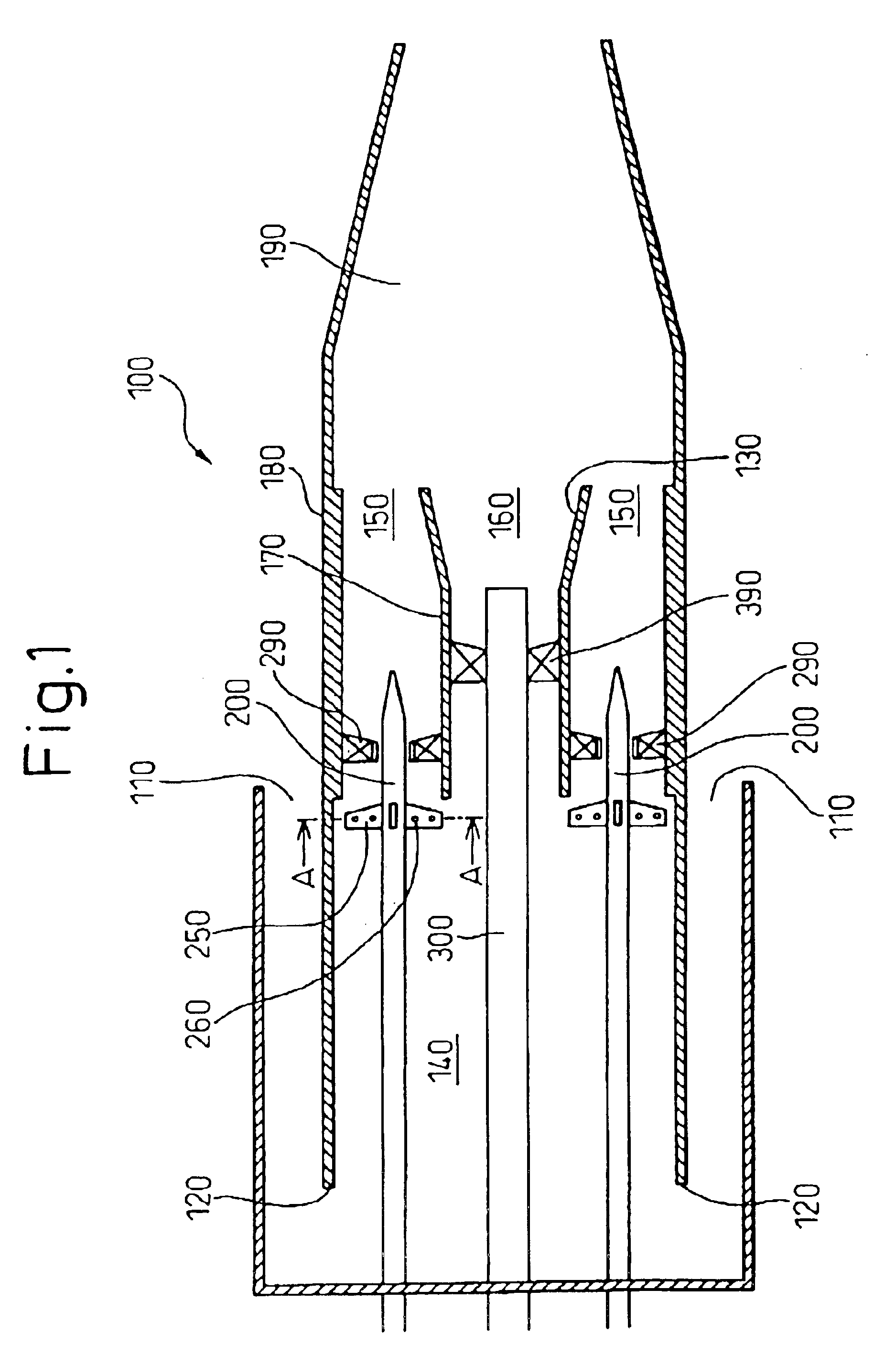
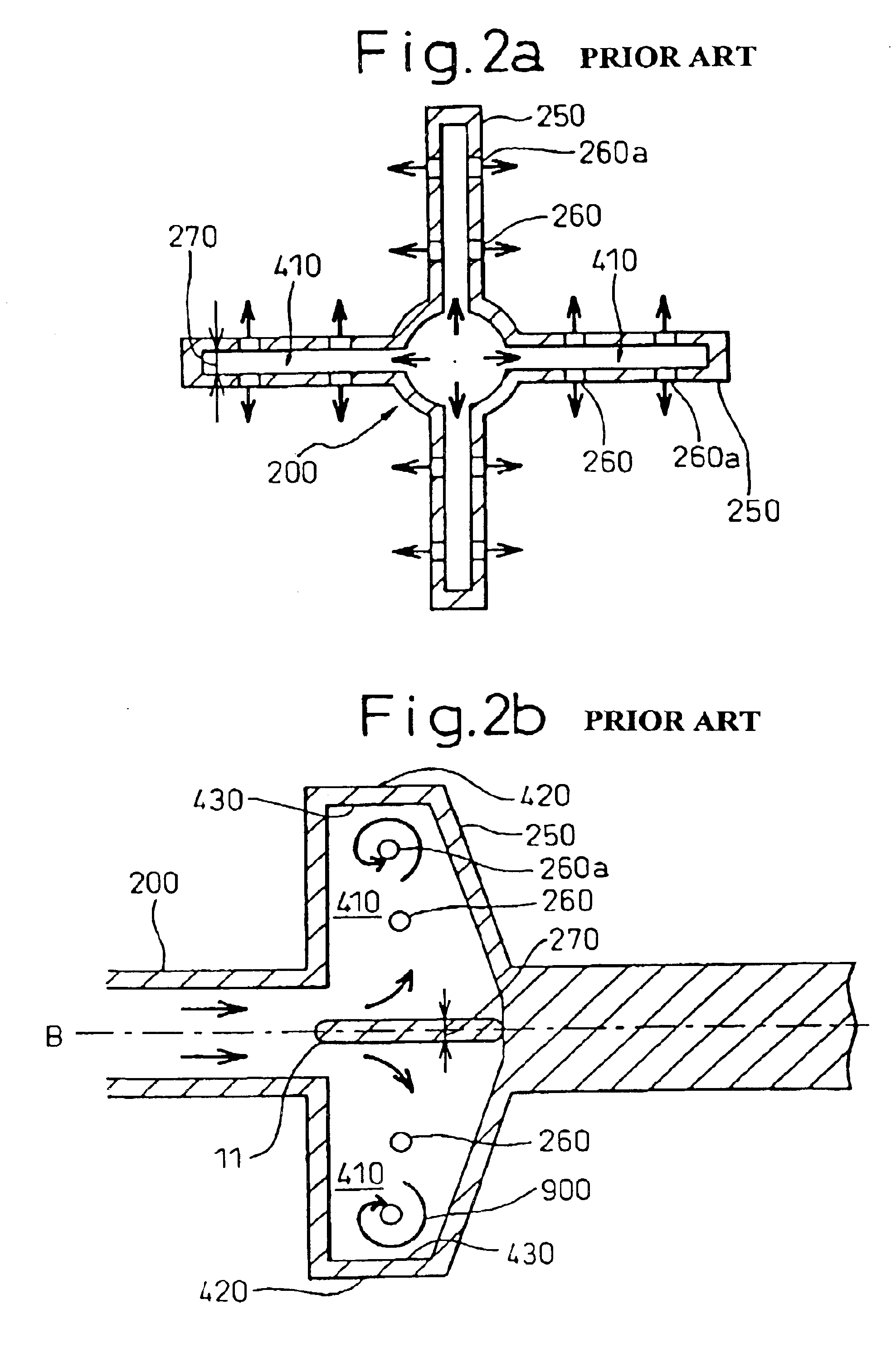
[0030]FIG. 3 is an axial direction sectional view of a fuel nozzle contained in a gas turbine combustor according to a first embodiment of the present invention. As in a known fuel nozzle 200, the fuel nozzle of the present invention is disposed in the combustor (not shown), and a swirler is provided around the fuel nozzle of the present invention. However, the swirler and the inner tube are omitted for easy understanding. As in the known fuel nozzle 200 described above, the fuel nozzle 200 is disposed, in an air passage to supply air (not shown), substantially parallel with the axis of the air passage. A fuel nozzle 20 has a rodlike body 21 and a plurality of hollow columns 25 extending from the rodlike body 2...


PUM


Abstract

There is provided a combustor comprising a fuel nozzle which is comprised of a rodlike body which has a fuel passage and which is located in an air passage; a plurality of hollow members which are connected to the fuel passage and which extend in radial directions from the rodlike body into the air passage; at least one injection port formed in each hollow member to inject a fuel from the fuel passage into the air passage; and a projection which extends from a farmost inner wall of each hollow member that is most distant from an axis of the rodlike body to the injection port that is most distant from the axis. A hole for leaking fuel that is connected to an air passage may be formed in a farmost inner wall of the hollow member that is more distant from an axis of a rodlike body than the injection port that is most distant from the axis, or may be formed to be adjacent to all the injection ports on an upstream or downstream side in the direction of the airflow. Thus, a vortex does not occur in the hollow column.

Description

BACKGROUND OF THE INVENTION[0001]1. Field of the Invention[0002]The present invention relates to a combustor containing a fuel nozzle to supply fuel. Particularly, it relates to a gas turbine combustor.[0003]2. Description of the Related Art[0004]FIG. 1 shows an axial direction sectional view of a combustor containing a known fuel nozzle disclosed in Japanese Patent Application No. 2001-173005. As shown in FIG. 1, a pilot nozzle 300 is provided on an central axis of inner tube 180 of a combustor 100. A plurality of fuel nozzles 200, which extend substantially parallel to the pilot nozzle 300, are equally spaced in a peripheral direction around the pilot nozzle 300. Fuel is supplied to the pilot nozzle 300 and fuel nozzles 200. A swirl vane or a swirler 290 is disposed around a rodlike body of the fuel nozzle 200. A plurality of hollow columns 250 which radially and outwardly extend from the sidewall of the fuel nozzle 200 are provided on the fuel nozzle 200. The hollow columns 250 a...

Claims


Application Information

Patent Timeline
Patent Type & Authority Patents(United States)
IPC IPC(8): F23R3/28F23D14/02F23D14/58
CPCF23R3/286F23D2210/00F23D2900/14004F23R2900/00014
Inventor SAITOH, KEIJIROUKAWANO, TAKASHINIINAI, HIDEMIKAWATA, YUTAKAMANDAI, SHIGEMIAOYAMA, KUNIAKI
Owner MITSUBISHI HEAVY IND LTD
Why Eureka
Try Eureka