

Reaction device for brake booster
a technology of brake booster and reaction device, which is applied in the direction of braking system, servomotor, transportation and packaging, etc., can solve the problems of significant modification of the internal structure, and achieve the effects of small size, low cost and modifiable boost level
- Summary
- Abstract
- Description
- Claims
- Application Information
AI Technical Summary
Benefits of technology
Problems solved by technology
Method used
Image

Examples
first embodiment
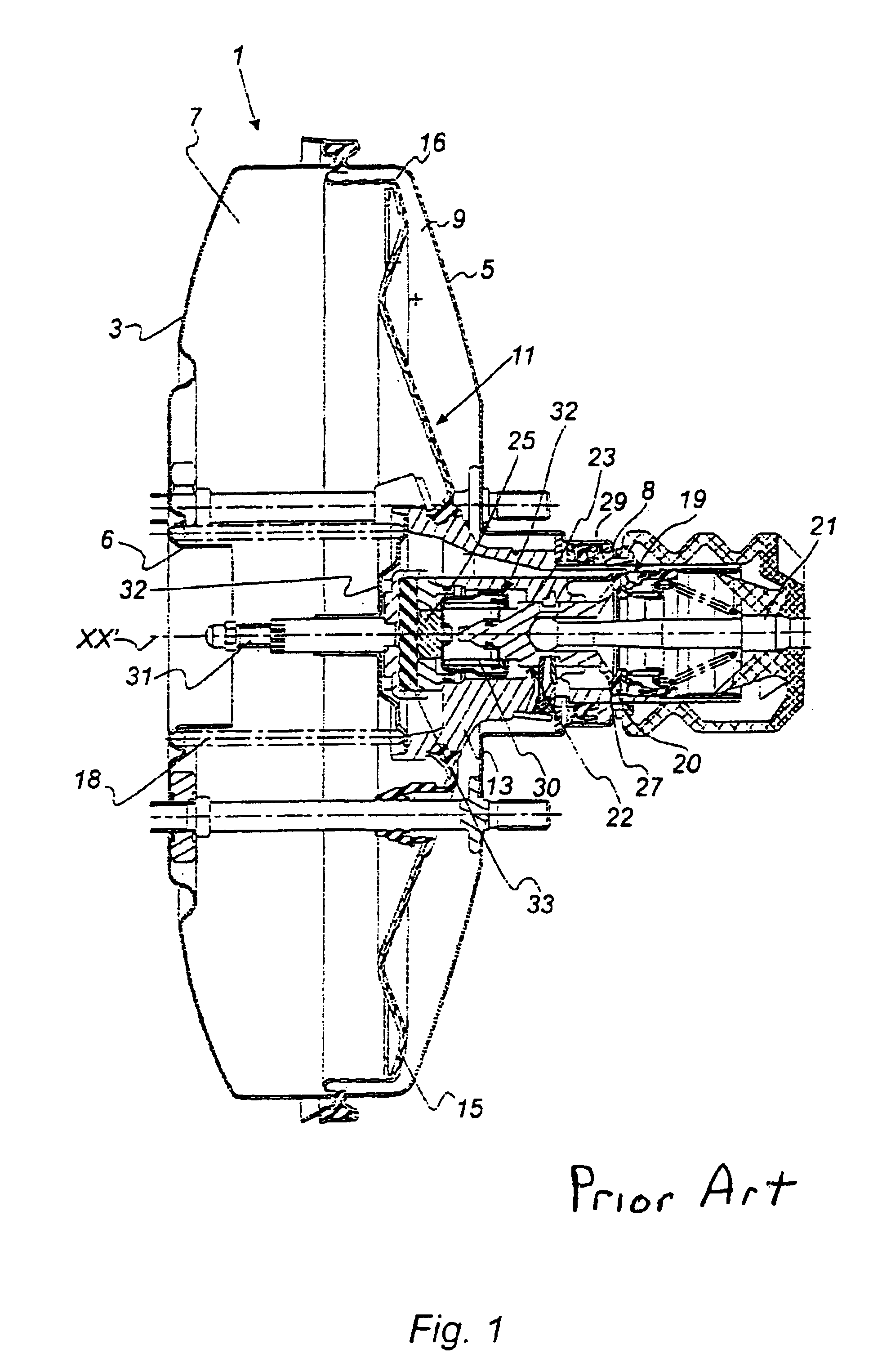
[0077]FIG. 3 shows a brake booster equipped with a reaction device according to the present invention, comprising a casing 1 formed of a first shell 3 and a second shell 5 each of which respectively has a central opening 6, 8 and which is divided into two chambers 7, 9 by a sealed moving wall 11. The moving wall 11 in its central part has a pneumatic piston 13 extending axially towards the rear and in its radially external part has a rigid skirt 15 crimped to the external periphery of the piston 13, sealing being achieved by means of a rolling seal 16 fixed hermetically to the casing 1 and to the pneumatic piston 13.
[0078]A spring 18 is mounted in compression between the rear face of the shell 3 and the front face of the piston 13 so as to return it at rest.
[0079]The front chamber 7 is connected by sealed means (not depicted) to a source of partial vacuum.
[0080]A three-way valve 19 is arranged in the cylindrical part of the pneumatic piston 13 and is controlled by means of a control...
second embodiment
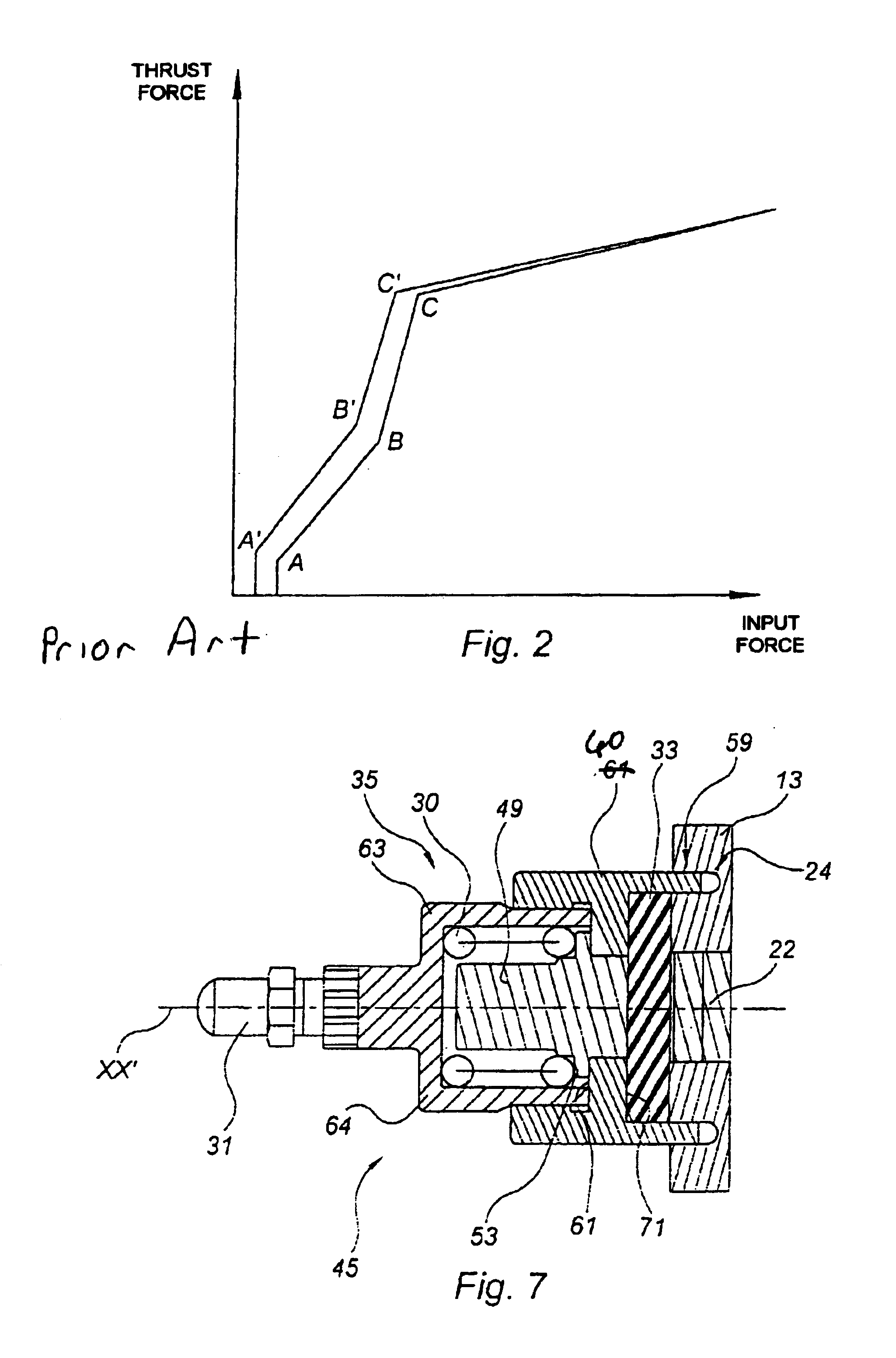
[0115]FIG. 8 shows a reaction device 135 according to the present invention, comprising a reaction disc 33, an elastic means 30 and means of prestressing an elastic means comprising a sleeve 72 equipped at a first end directed forwards with a first part 73 of smaller diameter and at a second end directed backwards with a second part 75 of larger diameter, the first part 73 being connected to the second part by a shoulder 77. The part 73 of smaller diameter comprises, at a forward facing end, an annular surface 79 extending inwards and delimiting a passage 74.
[0116]The push rod 31 comprises at a forward facing first end a first part 78 of smaller cross section and, at a second end which is the opposite end to the first end, a second part of larger cross section 78′ forming a base 80 of outside diameter smaller than the inside diameter of the larger-diameter second part 75, the space between the base 80 and the sleeve 75 defining an annular passage 76. The piece 78 is fixed into the p...
third embodiment
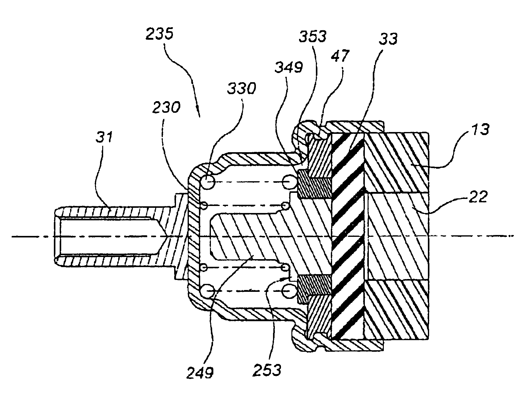
[0127]FIG. 9 shows a reaction device which once again allows the boost ratio of the booster to be modified and in which the pneumatic piston 13 and the distributor 22 are depicted in part.
[0128]The reaction device 235 differs from the reaction device 35 of the first embodiment in that it comprises a composite floating piece 49 comprising a central first piece 249 and an annular second piece 349 sliding about the first piece 249. The first piece 249 includes stop means 253 that rest against and engage the front face of the second piece 349 and the second piece 349 includes stop means 353 that rest against and engage against the annular washer 47. A first spring 230 is mounted in compression between the rear face of the end wall of the cage 37 and the stop means 253, a second spring 330, with a prestress higher than that of the first spring 230, is mounted in compression between the rear face of the end wall of the cage 37 and the stop means 353, the spring 330 has an inside diameter ...
PUM
 Abstract
Description
Claims
Application Information