
Locking clamp

a clamp and lock technology, applied in the field of clamps, can solve the problems of reducing the life of the clamp, clamps releasing, and clamp components wear and potential deformation, and achieve the effect of increasing strength and being more robus

Active Publication Date: 2005-08-23
DELAWARE CAPITAL FORMATION
View PDF5 Cites 40 Cited by
  • Summary
  • Abstract
  • Description
  • Claims
  • Application Information

AI Technical Summary

Benefits of technology

[0016]One advantage of the present invention is that the locking clamp is more robust and removes any bends and replaces them with straight parts in the clamp.
[0017]Another advantage of the present invention is that the locking clamp has increased strength.
[0018]Still a further advantage of the present invention is that the locking clamp provides for interchangeability of parts.
[0019]Another advantage of the present invention is that the locking clamp includes a locking mechanism that positively locks the clamp in its fully engaged position.
[0020]Another advantage of the present invention is that the locking mechanism of the locking clamp can only become disengaged with specific action taken by an operator of the clamp.
[0021]Still a further advantage of the present invention is that the locking mechanism is capable of use by both right handed and left handed operators of the clamp.

Problems solved by technology

Other prior art clamps create a holding force by passing the links of the toggle clamps to an over center position, the over center position subjects the links and the pivot points of the clamp to very high loads resulting in increased wear and potential deformation of the clamp components thereby reducing the life of the clamp.
There have been some problems with some prior art clamps releasing due to vibration and other unforeseen forces during the use of the clamps.
These bends may reduce performance and strength of the clamp by amounts up to 30 to 40 percent.
Some of these clamps also include parts that have bends that are not interchangeable and have to be put together in precise positions, thus increasing the cost of labor of assembling the clamps.
Also many of these prior art clamps do not include a positive locking mechanism which will ensure the clamp is locked and not capable of being opened when it is in its fully engaged position.
The positive locking of the clamp is necessary in manufacturing environments where the unexpected disengagement of a clamp may produce hazards and other down time on manufacturing lines because of such unexpected releases.

Method used


Image

  • Locking clamp
  • Locking clamp
  • Locking clamp

Examples


Embodiment Construction

)

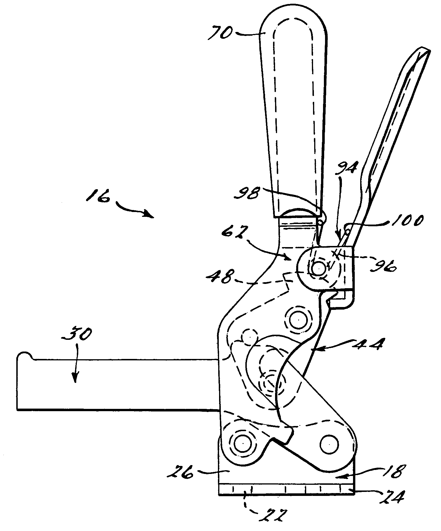
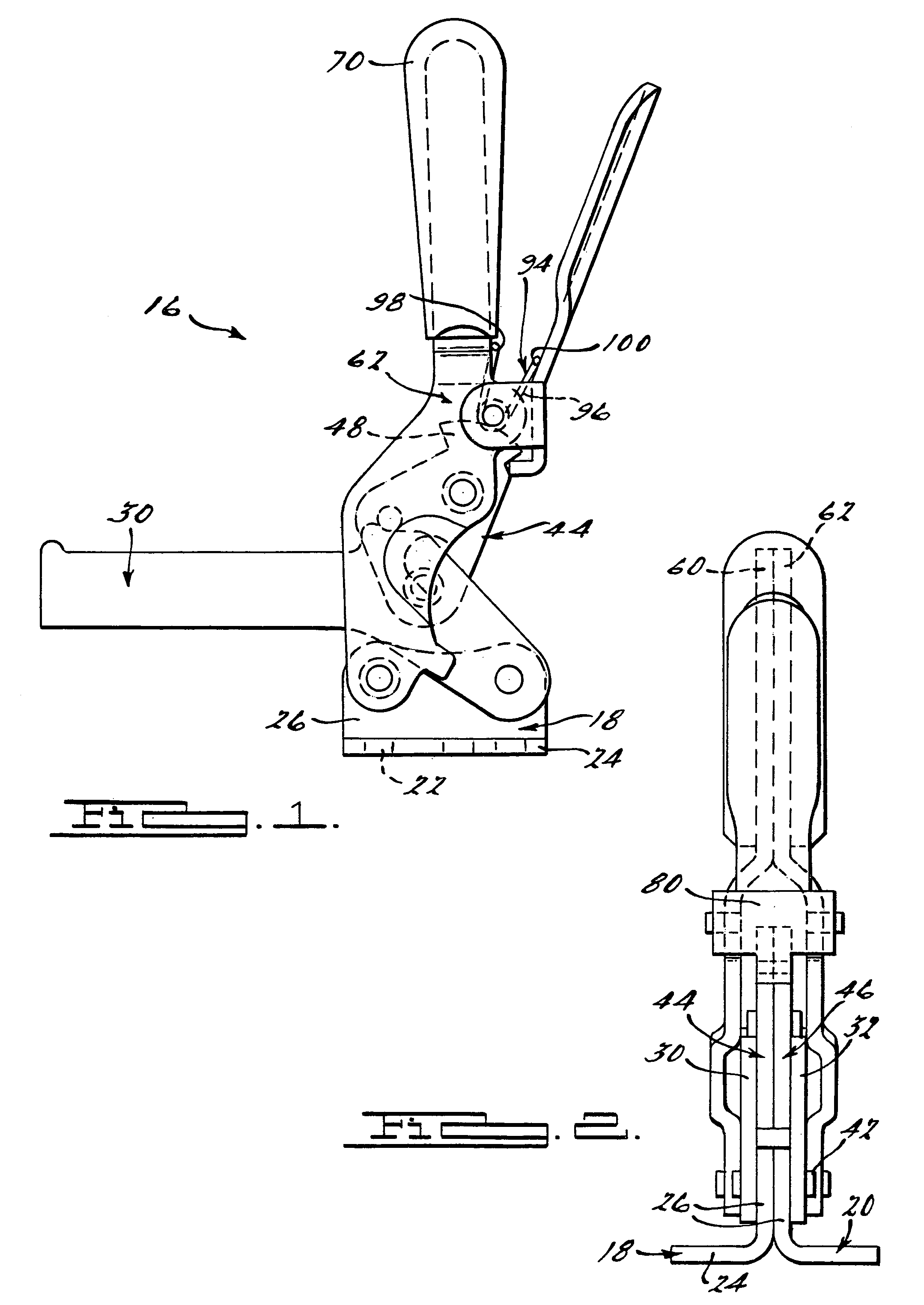
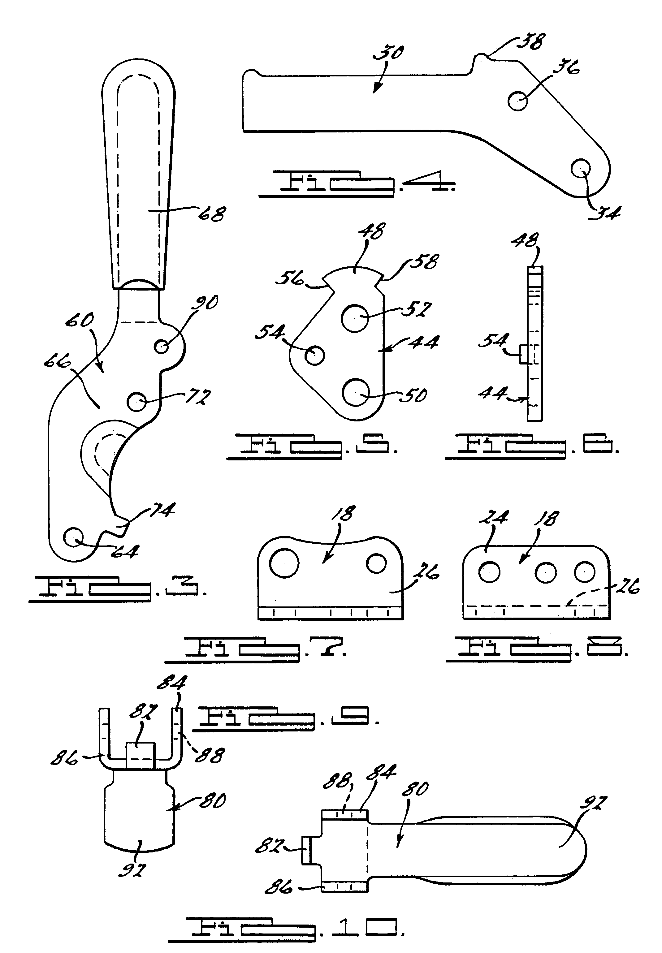
[0038]The invention will now be described with reference to the drawings, wherein like numerals in different drawing figures indicate like elements.

[0039]FIGS. 1 through 10 show one embodiment of a locking clamp 16 according to the present invention. The clamp 16 includes a first and second base member 18, 20 with each base member 18, 20 generally having an L-shaped cross section. The base members 18, 20 include a plurality of orifices 22 through a bottom surface thereof and a side surface thereof. The bottom flange 24 of the base member 18, 20 generally has two orifices 22 therein and those orifices are used to secure, via any known fastener, the clamp 16 to a bench, tool or other work device. The upright portion 26, 28 of the base member 18, 20 includes a first and second orifice that are used to connect to the other parts of the clamp 16. The base members 18, 20 are placed such that the upright portion 26 of the base members 18, 20 are in contact with one another and the bottom ...


PUM


Abstract

A locking clamp that includes a base member. The locking clamp further includes a bar pivotally connected to the base member on one end thereof. A handle is pivotally connected to a base member on an end opposite of the bar. The clamp further includes a link connected to the handle and the bar. The link has a stopper extending from a side thereof. The clamp also includes a locking lever for use in locking the clamp in its fully closed / fully engaged position.

Description

BACKGROUND OF THE INVENTION[0001]1. Field of the Invention[0002]The present invention relates to clamps generally, and more particularly, relates to a locking manual hold down clamp.[0003]2. Description of Related Art[0004]Toggle and hold down clamps have been used and known in the art for many years. A typical hold down or toggle clamp includes a clamping arm which pivots between a released and clamped position. The clamps are used to hold work pieces in place for processing, for clamping two objects to one another, or for clamping an object to a work table or other surface. Toggle and hold down clamps generally are quickly engageable and disengageable to the work piece or object being held. They also provide a considerable holding and clamping force which enables them to hold the work piece or object securely where needed.[0005]Many of these prior art devices hold the clamp position to a variety of means, these means include maintaining the force applied to the bar or arm of the c...

Claims


Application Information

Patent Timeline
Patent Type & Authority Patents(United States)
IPC IPC(8): B25B5/00B25B5/12
CPCB25B5/12
Inventor DYKSTRA, HENRY
Owner DELAWARE CAPITAL FORMATION
Features
  • Generate Ideas
  • Intellectual Property
  • Life Sciences
  • Materials
  • Tech Scout
  • Unparalleled Data Quality
  • Higher Quality Content
  • 60% Fewer Hallucinations
Learn More