Adhesive patterns for vehicle wheel assemblies

a technology for adhesive patterns and wheels, applied in the field of adhesive patterns for vehicle wheel assemblies, can solve the problems of affecting the cure time of wheels, the use of adhesives, and the continuous coating of adhesives between wheels

Inactive Publication Date: 2005-08-23
LACKS INDUSTRIES INC
View PDF42 Cites 13 Cited by
  • Summary
  • Abstract
  • Description
  • Claims
  • Application Information

AI Technical Summary

Benefits of technology

[0017]assembling the wheel cover to the wheel to cause the adhesive to contact both the outboard surface of the wheel and the inner surface of the wheel cover and thereby enable the adhesive pattern to secure the wheel cover to the wheel and define a space between the wheel cover and wheel which is not filled with adhesive,
[0022]a cured adhesive between the wheel and wheel cover which bonds the wheel and wheel cover together with a space between the wheel and wheel cover which space is partially filled with the cured adhesive, the cured adhesive being provided in a pattern allows ambient fluids to enter throughout the space between the wheel cover and the wheel which is not filled with adhesive and exit the space.

Problems solved by technology

The decorative cover in Derleth is configured to have variations in contour in a direction transverse to the axis of the wheel which exceed the variations in the rim and / or disc contour of the wheel, which variations would be extremely difficult and expensive, if not impossible, to stamp or draw in the disc of the wheel.
The inclusion of turbine openings in wheels and wheel covers creates problems with the use of adhesives.
In the case of air-cured and moisture-cured adhesives, it has been discovered that the use of continuous coatings of the adhesives between wheel covers and a wheels adversely effects cure time.
The concern remains that if such water, mud and debris enter any voids, gaps or other spaces between the wheel covers and the wheels, it will eventually cause corrosion to occur between the wheel covers and wheel and result in detachment of the wheel cover or at an unsightly appearance.

Method used


Image

  • Adhesive patterns for vehicle wheel assemblies
  • Adhesive patterns for vehicle wheel assemblies
  • Adhesive patterns for vehicle wheel assemblies

Examples


Embodiment Construction

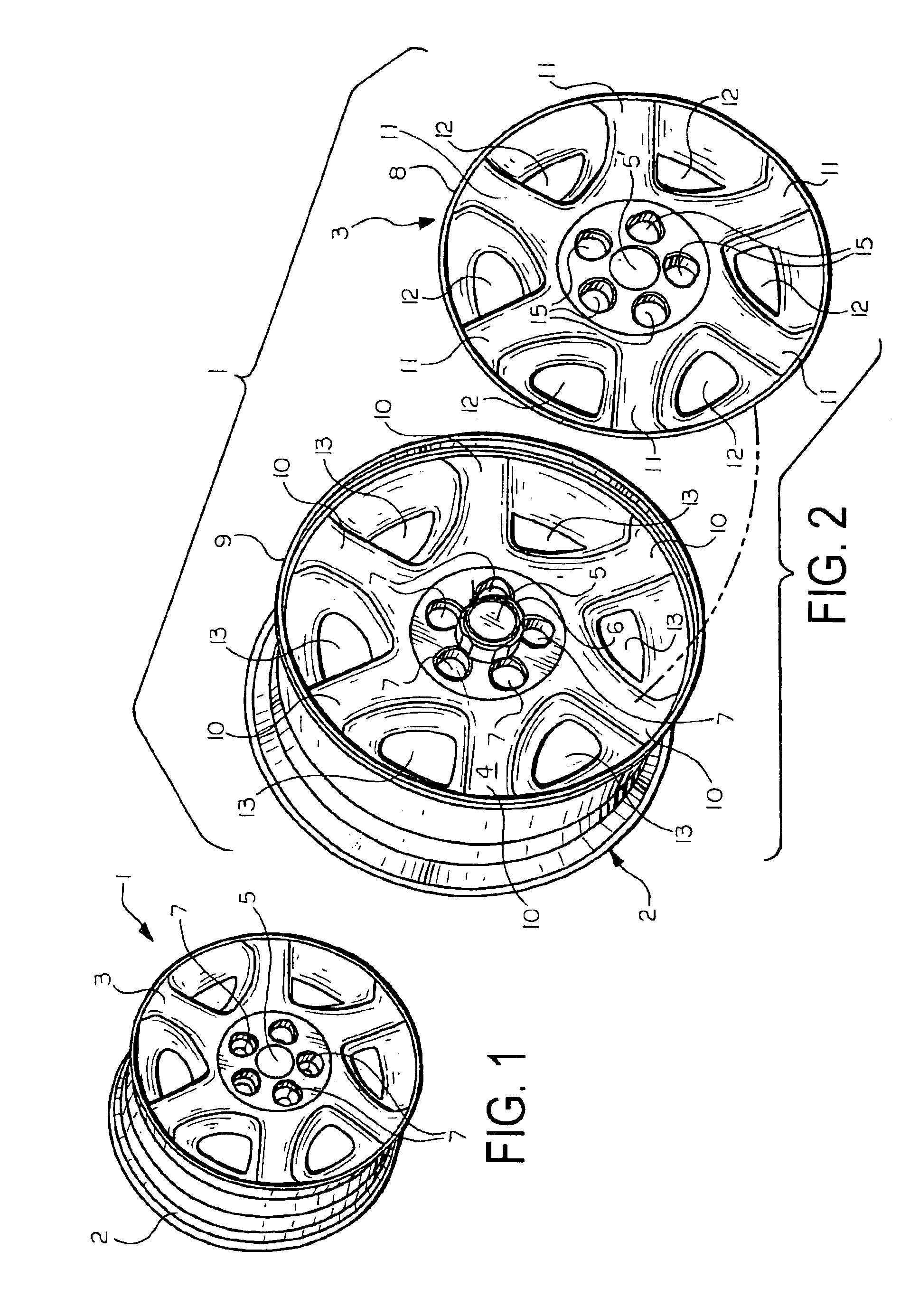
[0030]FIG. 1 is a perspective view of a wheel assembly according to one embodiment of the present invention. The wheel assembly which is generally identified by reference numeral 1 includes a wheel 2 that can be made of aluminum, magnesium, steel, or other material conventionally used for manufacturing vehicle wheels. A decorative wheel cover 3 is bonded to the otherwise outer exposed surface 4 (See FIG. 2) of wheel 2. The wheel cover 3 is a solid panel of a high-impact plastic that has a high temperature resistance or can be a thin metallic panel such as stainless steel that, in either case has a finished outer surface that can be painted, textured or plated, e.g. chrome plated as desired. An advantage of using a high-impact plastic material such as a combination of polycarbonate and ABS having is that wheel covers 3 made from such materials can be injection molded.

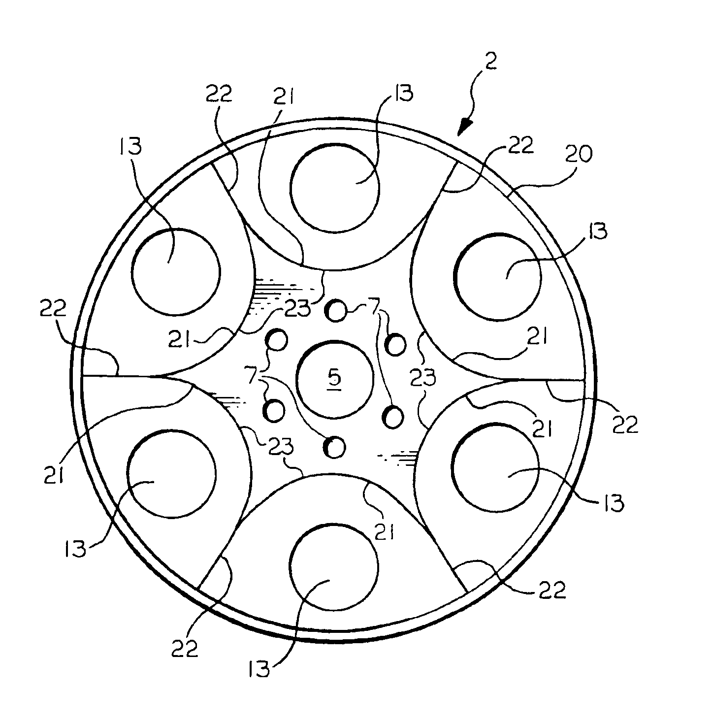
[0031]Wheel 2 is of the type which includes a small central opening 5 in the wheel hub 6 and a plurality of exposed lu...


PUM


Abstract

Adhesive patterns are applied to one of an outboard side of a wheel and an inner surface of a decorative wheel cover and used to bond the decorative wheel cover to the wheel with a spaced therebetween that is partially filled with the cured adhesive. The decorative wheel cover and wheel each include aligned lug nut apertures and aligned decorative openings. The adhesive patterns are configured to allow ambient fluids to enter throughout the space between the decorative wheel cover and the wheel (and leave) which is not filled with the cured adhesive to prevent corrosion from occurring between the decorative wheel cover and wheel.

Description

TECHNICAL FIELD[0001]The present invention relates to vehicle wheels that have decorative wheel covers secured over the wheels for aesthetic purposes. More specifically, the present invention relates to methods for adhesively securing decorative wheel covers to wheels which methods involve the use of functional adhesive patterns.BACKGROUND ART[0002]Wheel assemblies that utilize wheel appliques to decorate the external or outboard surfaces of plain steel wheels are well known and are far less expensive to produce than decorative wheels that have to be formed and finished.[0003]Wheel appliques can be secured to wheels by various mechanical engaging structures and / or by adhesives. U.S. Pat. No. 5,664,845 to Maloney et al. discloses a vehicle wheel cover retention system in which the annular lip of the wheel cover is configured to spring outwardly into a groove provided in the inner surface of the wheel. U.S. Pat. No. 5,595,423 to Heck et al. discloses a vehicle wheel cover retention sy...

Claims


Application Information

Patent Timeline
Patent Type & Authority Patents(United States)
IPC IPC(8): B60B7/00B60B7/06
CPCB60B7/06B60B7/18
Inventor CUTCHER, DOUGLAS J.HOGAN, SCOTT A.
Owner LACKS INDUSTRIES INC
Why Eureka
Try Eureka