Gas turbine shroud structure

a gas turbine and shroud technology, applied in the direction of machines/engines, liquid fuel engines, light and heating apparatus, etc., can solve the problems of inability to further reduce the cooling air or weight, metal components have already reached their limitations, and cannot be further reduced. to achieve the effect of enhancing gas turbine capability and preventing the generation of high thermal stress

Inactive Publication Date: 2005-08-23
IHI CORP
View PDF9 Cites 89 Cited by
  • Summary
  • Abstract
  • Description
  • Claims
  • Application Information

AI Technical Summary

Benefits of technology

The purpose of this invention is to create a new design for the part of a gas turbine called the shroud that prevents damage from very hot gases and allows it to expand without causing too much pressure or heat. This helps improve the performance of the engine and make sure it runs safely.

Problems solved by technology

The technical problem addressed in this patent is how to improve the performance of gas turbines while reducing both cooling air amounts and weights without reaching limits set forth by current materials technology.

Method used


Image

  • Gas turbine shroud structure
  • Gas turbine shroud structure
  • Gas turbine shroud structure

Examples


Embodiment Construction

[0033]A preferred embodiment of the present invention will be described hereinafter with reference to the drawings. It is to be noted that common portions in the respective drawings are denoted with the same reference numerals, and redundant description is omitted.

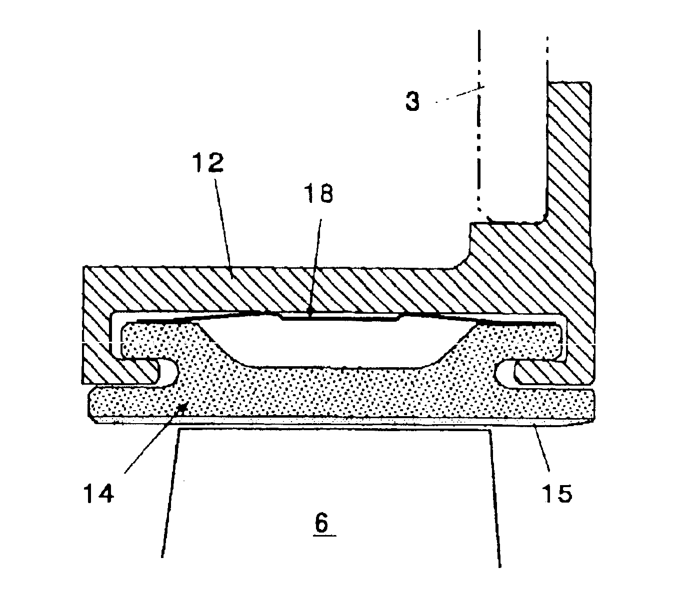
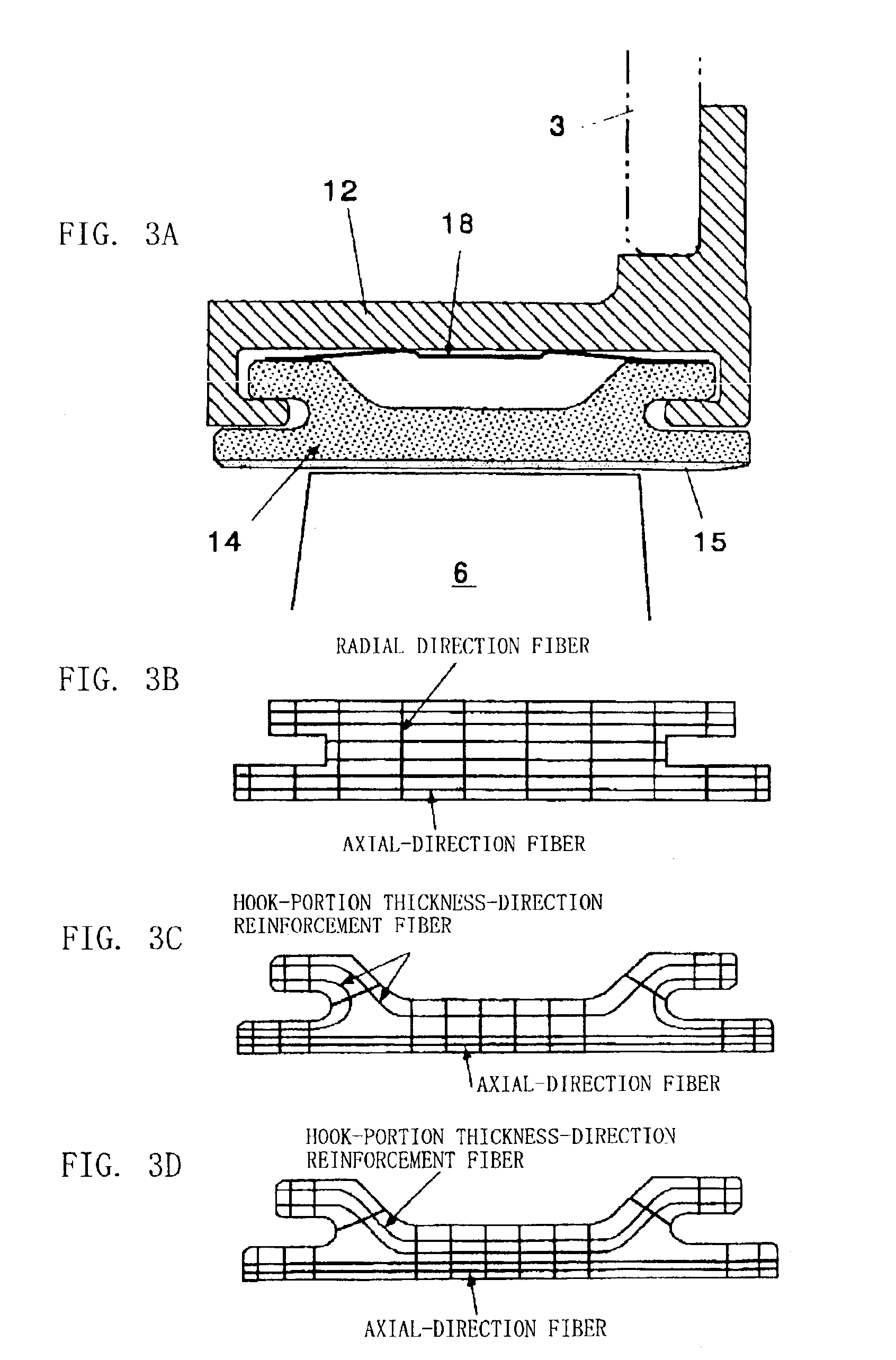
[0034]FIGS. 3A to 3D are sectional views showing the gas turbine shroud structure according to the present invention. As shown in the drawings, the gas turbine shroud structure of the present invention includes a shroud support component 12, shroud segment 14, and restricting spring 18.

[0035]The shroud support component 12 is a metal component, and is attached to the inner surface of a gas turbine casing 3 via bolts.

[0036]The shroud segment 14 is a circular arc member divided in a peripheral direction, and is fixed to the inner surface of the shroud support component 12. As shown in FIGS. 3B, 3C, 3D, the shroud segment 14 is formed of a ceramic composite material using a laminated and stitched two-dimensional fabric, or a ...


PUM

PropertyMeasurementUnit
Thicknessaaaaaaaaaa
Elasticityaaaaaaaaaa
Heataaaaaaaaaa

Abstract

There is disclosed a gas turbine shroud structure comprising: a shroud support component 12 attached to an inner surface of a gas turbine casing 3; a shroud segment 14 divided in a peripheral direction and supported by the inner surface of the shroud support component; and a heat-resistant restricting spring 18 held between the shroud segment and shroud support component to urge the shroud segment inwards in a radial direction. The shroud segment 14 is formed of a ceramic composite material, and includes a coating layer 15 having heat insulation and impact absorption effect on an inner surface of the segment.

Description


Claims


Application Information

Patent Timeline
Owner IHI CORP
Why Eureka
Try Eureka