Hydropower generation apparatus and method

a technology of hydropower and apparatus, applied in the direction of machines/engines, electric generator control, water cleaning, etc., can solve the problems of rare, if at all, commercial use of hydropower devices, such as those disclosed in the aforementioned patents, and few successful practical applications of these machines

Inactive Publication Date: 2005-08-23
BEASTON STEVEN D
View PDF27 Cites 27 Cited by
  • Summary
  • Abstract
  • Description
  • Claims
  • Application Information

AI Technical Summary

Problems solved by technology

In this regard, although various hydropower machines have been developed and / or proposed in recent times, few of these machines have been successful in practical application, a notable exception being a conventional turbine (i.e. located at a dam).
It is believed that known hydropower devices, such as those disclosed in the aforementioned patents, are not often, if at all, commercially employed primarily due to complexity, inherent inefficiencies, and / or exorbitant manufacturing or maintenance costs.

Method used


Image

  • Hydropower generation apparatus and method
  • Hydropower generation apparatus and method
  • Hydropower generation apparatus and method

Examples


Embodiment Construction

[0031]For a more complete understanding of the present invention and advantages thereof, reference is now made to the following description of various illustrative and non-limiting embodiments thereof, taken in conjunction with the accompanying drawings in which like reference numbers indicate like features.

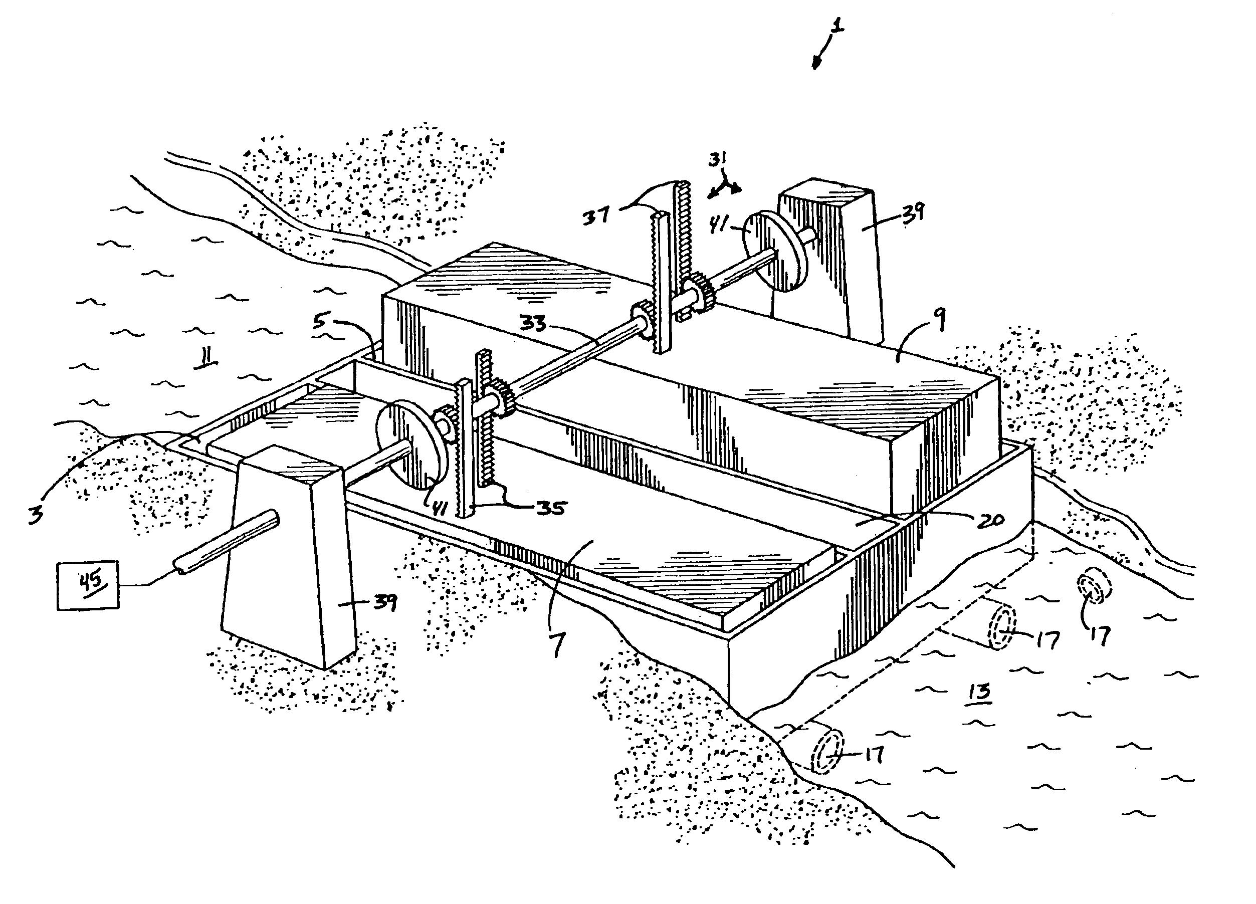
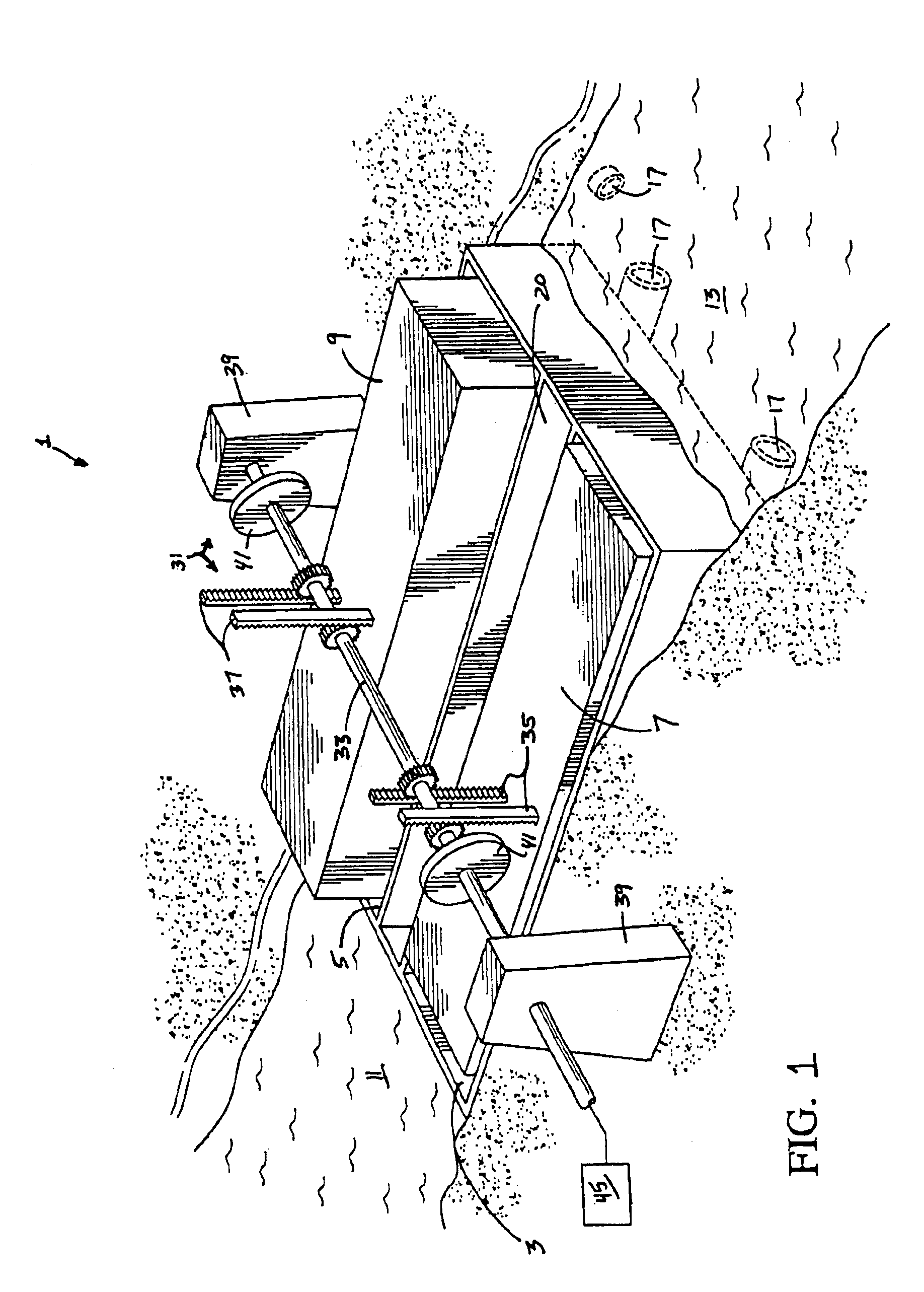
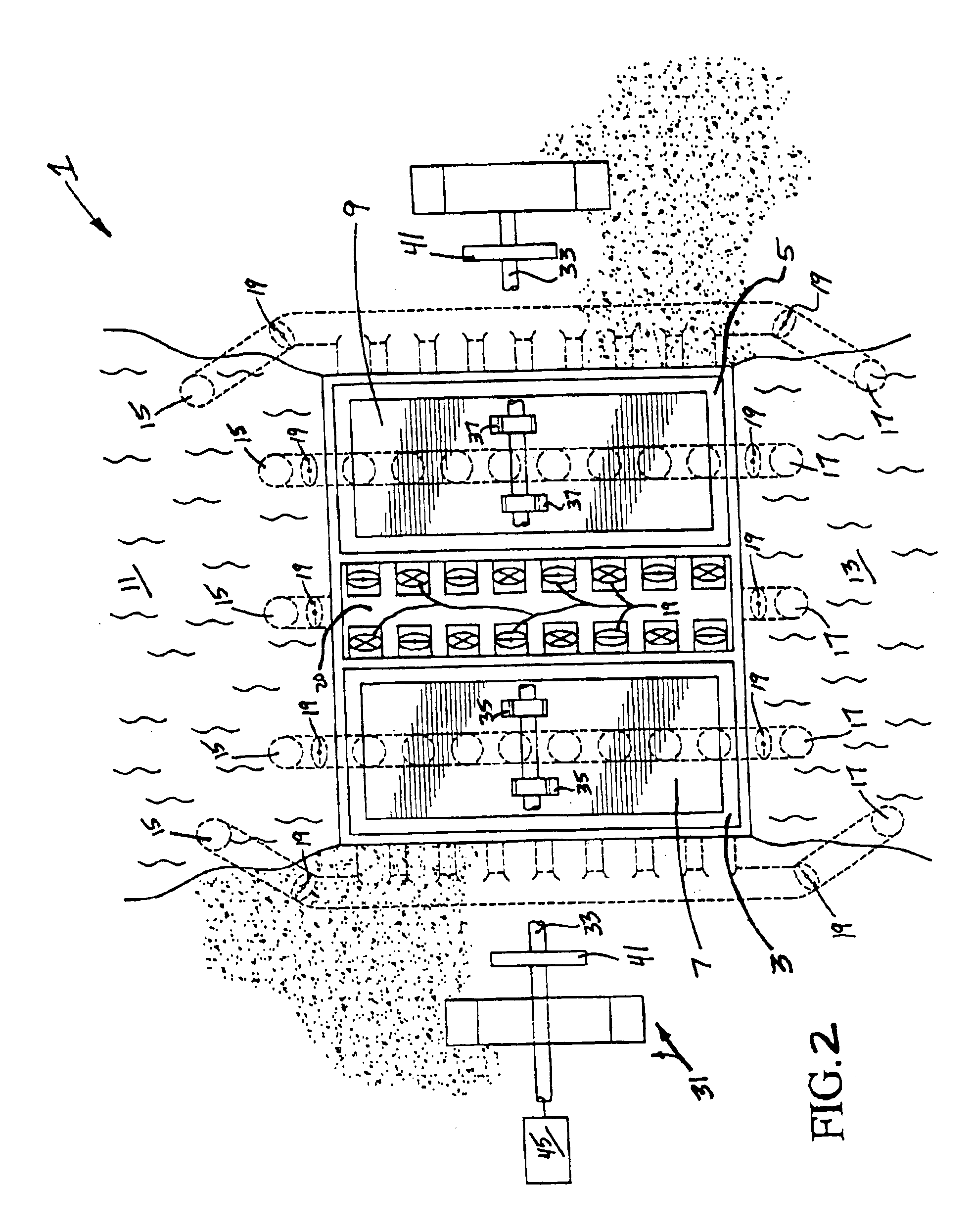
[0032]Referring initially to FIGS. 1 and 2, an exemplar embodiment of a hydropower apparatus 1 according to the subject invention is illustrated therein. Generally speaking, hydropower apparatus 1 comprises first and second water holding chambers 3 and 5 which contain first and second buoyant objects 7 and 9 respectively. In the illustrated embodiment, chambers 3 and 5 are large rectangular cavities, the dimensions of which can be selected according to various factors including cost, the amount of power to be generated, or the space availability at the site location. Example dimensions for the cavities as contemplated for practical use are 600×200 feet. Buoyant objects 7 and 9 ar...


PUM


Abstract

Apparatus and methods for generating power utilizing the flow of water from an upper water body to a lower water body in order to generate an upward buoyant force on at least one buoyant object located in a chamber. In preferred embodiments, water is recycled between at least two chambers which generate upward and downward strokes of at least two buoyant objects.

Description

RELATED APPLICATION DATA[0001]This application is a continuation-in-part of U.S. patent application Ser. No. 10 / 682,091, filed Oct. 10, 2003 now U.S. Pat. No. 6,831,373, similarly titled, and invented by Steven D. Beaston, the text of which is hereby incorporated by reference.FIELD OF THE INVENTION[0002]This invention relates to apparatus and methods for generating power utilizing the flow of water from an upper water body to a lower water body in order to generate an upward buoyant force on at least one buoyant object located in a chamber. In preferred embodiments, water is recycled between at least two chambers which generate upward and downward strokes of at least two buoyant objects.BACKGROUND OF THE INVENTION[0003]Because the supply of fossil fuels, natural gas, and other natural fuels is finite and because the processing and / or consumption of such fuels produces significant detrimental amounts of pollution, alternatives to such fuels have been experimented with, and in some ca...

Claims


Application Information

Patent Timeline
Patent Type & Authority Patents(United States)
IPC IPC(8): F03B17/02F03B17/00F03BF03B13/10
CPCF03B17/025Y02E10/20Y02E10/28Y02E10/30
Inventor BEASTON, STEVEN D.
Owner BEASTON STEVEN D
Why Eureka
Try Eureka