Data communication over a power line

a power line and data technology, applied in the direction of cables between relatively moving parts, instruments, wireless systems/telephones, etc., can solve the problem that non-electrically conducting signals may have properties that do not provide imminent danger

Inactive Publication Date: 2005-08-23
CURRENT TECH
View PDF359 Cites 145 Cited by
  • Summary
  • Abstract
  • Description
  • Claims
  • Application Information

AI Technical Summary

Benefits of technology

[0008]The invention is directed to communicating data signals over a power line. A signal is received from a first portion of the power line and at least a portion of the signal is converted to a non-electrically conducting signal. The n

Problems solved by technology

In this manner, the non-electrically conducting signal may have p

Method used


Image

  • Data communication over a power line
  • Data communication over a power line
  • Data communication over a power line

Examples


Embodiment Construction

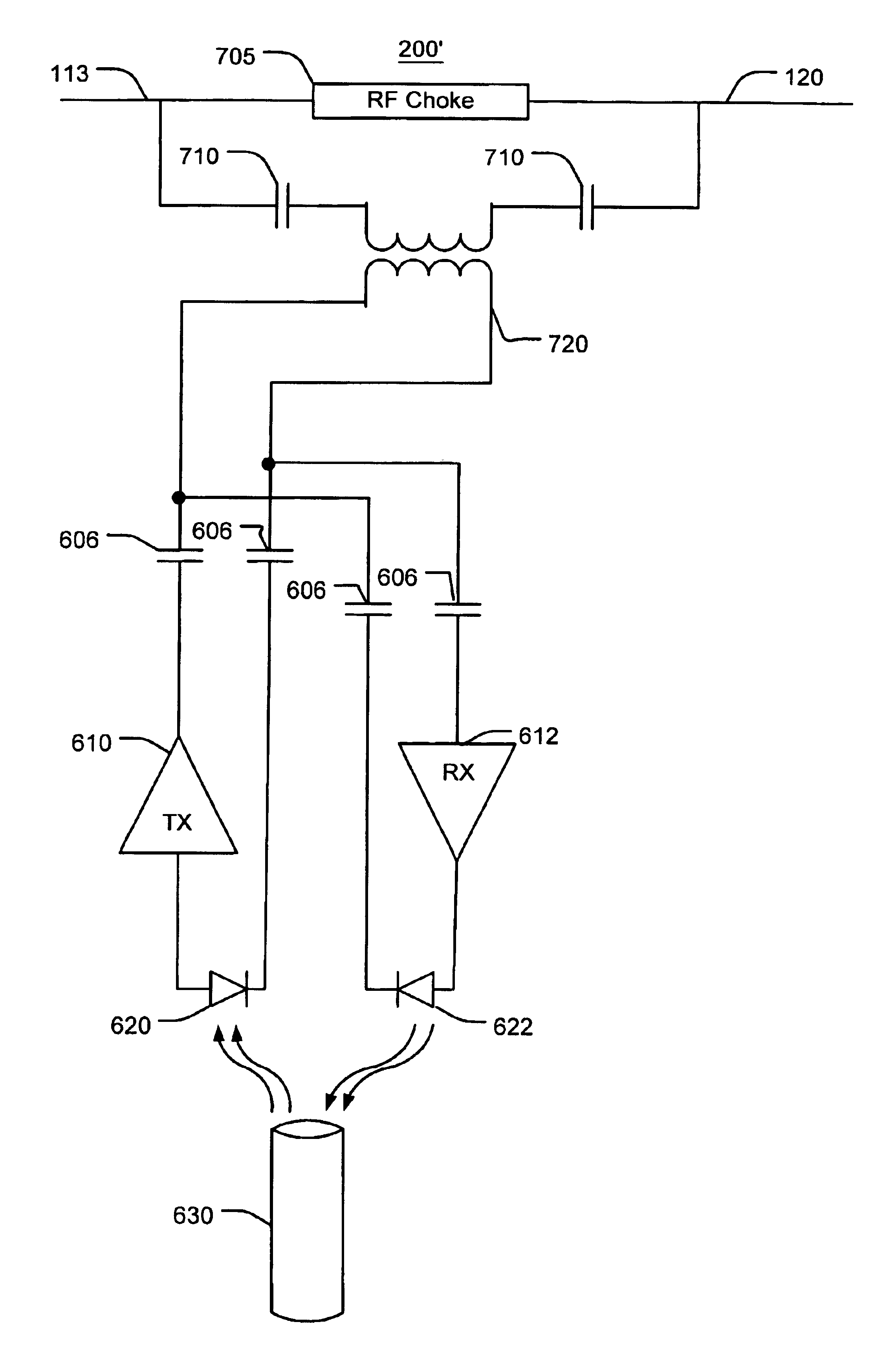
[0030]A power line coupler and a power line bridge communicate data signals across a transformer that would otherwise filter the data signals from passing through the transformer. Further, the power line coupler provides high electrical isolation between the transformer primary side and secondary side, thereby preventing substantial power flow through the power line coupler and the power line bridge. It should be appreciated that the functionality of the power line coupler and the power line bridge can be included in one device or distributed in more than one device. The power line coupler may include a power line coupling device that communicates data signals with a power line, circuitry to condition the data signal, circuitry to handle bi-directional signal transfer, circuitry to enable the use of an electrical isolator, circuitry to provide operational power from the power line, and may be designed to be self-contained. The power line coupler may include circuitry to communicate ...


PUM


Abstract

A signal is received from a first portion of a power line and at least a portion of the signal is converted to a non-electrically conducting signal. The non-electrically conducting signal may be communicated to a non-electrically conductive communication path. In this manner, the non-electrically conducting signal may have properties that do not provide imminent danger from human contact.

Description

CROSS REFERENCE TO RELATED APPLICATIONS[0001]This Application: claims benefit of U.S. provisional Application Ser. Nos. 60 / 268,519 and 60 / 268,578 both filed Feb. 14, 2001.FIELD OF THE INVENTION[0002]The invention generally relates to data communication over power lines and more particularly, to devices and methods for communicating data signals with the power lines.BACKGROUND OF THE INVENTION[0003]A well-established power distribution system exists throughout most of the United States and other countries. The power distribution system provides power to customers via power lines. With some modification, the infrastructure of the existing power distribution system can be used to provide data communication in addition to power delivery. That is, data signals can be carried by the existing power lines that already have been run to many homes and offices. The use of the existing power lines may help reduce the cost of implementing a data communication system. To implement the data commun...

Claims


Application Information

Patent Timeline
IPC IPC(8): G02B6/48G02B6/46H02G11/02H02G11/00H04B3/54H04B3/56G02B6/42
CPCG02B6/483H02G11/02H04B3/54H04B3/542H04B3/56G02B6/4246H04B2203/5416H04B2203/5441H04B2203/5445H04B2203/5483H04B2203/5487
Inventor KLINE, PAUL A.
Owner CURRENT TECH
Why Eureka
Try Eureka