Wind guard latch retainer

a latch retainer and wind guard technology, applied in the field of hay balers, can solve the problems of wind guard pipe and tines being too close to the pickup mechanism, plugging the pickup mechanism, and the tines of wind guards being too far away from the pickup mechanism to protect the small windrow, etc., to achieve carefree maintenance, low manufacturing cost, and durable construction

Active Publication Date: 2005-08-30
CNH IND AMERICA LLC +1
View PDF14 Cites 21 Cited by
  • Summary
  • Abstract
  • Description
  • Claims
  • Application Information

AI Technical Summary

Benefits of technology

[0012]It is yet another object of this invention to provide an improved latching mechanism for the wind guard pipe of an agricultural crop pickup th

Problems solved by technology

If the wind guard is adjusted for small windrows and a large windrow is encountered, the wind guard pipe and tines may be too close to the pickup mechanism to accommodate the large windrow.
This could cause plugging of the pickup mechanism.
If the wind guard is adjust

Method used


Image

  • Wind guard latch retainer
  • Wind guard latch retainer
  • Wind guard latch retainer

Examples


Embodiment Construction

[0021]Many of the fastening, connection, processes and other means and components utilized in this invention are widely known and used in the field of the invention described, and their exact nature or type is not necessary for an understanding and use of the invention by a person skilled in the art, and they will not therefore be discussed in significant detail. Also, any reference herein to the terms “left” or “right” are used as a matter of mere convenience, and are determined by standing at the rear of the machine facing in its normal direction of travel. Furthermore, the various components shown or described herein for any specific application of this invention can be varied or altered as anticipated by this invention and the practice of a specific application of any element may already by widely known or used in the art by persons skilled in the art and each will likewise not therefore be discussed in significant detail.

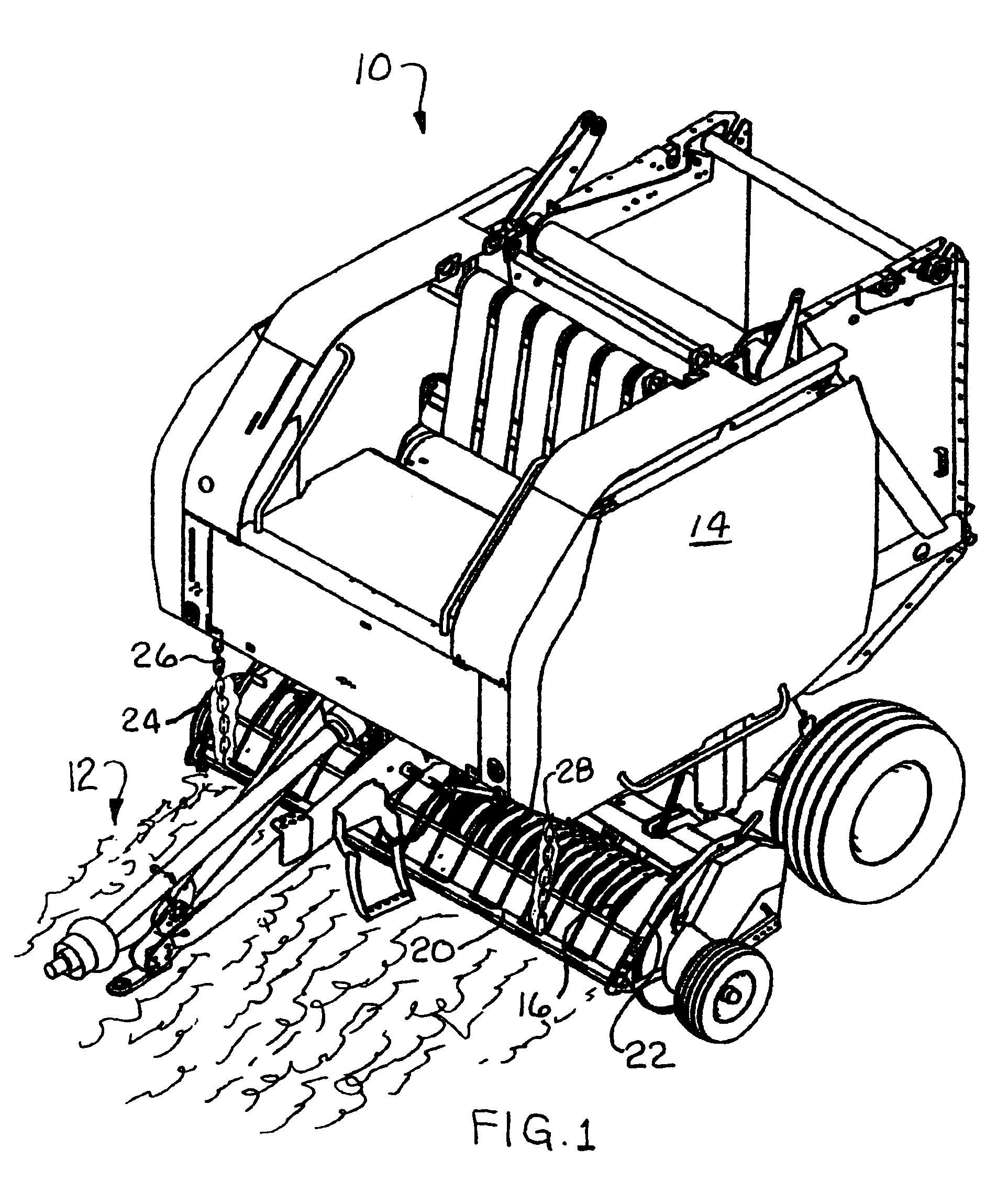
[0022]FIG. 1 shows an agricultural round baler 10 being p...


PUM


Abstract

A latch retainer mechanism for securely holding the windrow pipe of an agricultural crop pickup.

Description

BACKGROUND OF THE INVENTION[0001]The present invention relates generally to hay balers, and more particularly to improved mechanism for retaining the latch on the wind guard of an agricultural crop pickup on a round baler.[0002]For many years agricultural balers have been used to consolidate and package crop material so as to facilitate the storage and handling of the crop material for later use. Usually, a mower-conditioner cuts and conditions the crop material for windrow drying in the sun. When the cut crop material is properly dried, a baler is pulled along the windrows to pick up the crop material and form it into conveniently sized and shaped round bales. More specifically, the windrow pickup of the baler gathers the cut and windrowed crop material and lifts it into the baling chamber. In a round baler, the baling chamber consists of a pair of opposing sidewalls with a series of belts that rotate and compress the crop material into a cylindrical shape. When the bale has achiev...

Claims


Application Information

Patent Timeline
IPC IPC(8): A01D43/00A01D89/00
CPCA01D89/008
Inventor MCCLURE, JOHN R.
Owner CNH IND AMERICA LLC
Why Eureka
Try Eureka