Pressure control system for low pressure operation

a control system and low-pressure technology, applied in fluid pressure control, process and machine control, instruments, etc., can solve the problem that the pressure control system type cannot meet the increasingly strict requirements in terms of accuracy and stability

Active Publication Date: 2005-08-30
HYDROGENICS CORP
View PDF7 Cites 9 Cited by
  • Summary
  • Abstract
  • Description
  • Claims
  • Application Information

AI Technical Summary

Benefits of technology

[0006]In accordance with the present invention, there is provided a pressure control system for controlling the pressure of a process fluid stream at a certain location, comprising: (a) a pressure regulator mounted downstream of an upstream process fluid line, the regulator having a closure member movable between open and closed positions for controlling process fluid flow through the fluid line, and a control chamber for housing an actuator fluid for acting on the closure member, wherein the position of the closure member changes in response to changes in the pressure of the actuator fluid housed in the control chamber; (b) an inspirator having an inlet, an outlet, and a throat between the inlet and outlet, the control chamber of the regulator being in flow communication with the throat of the inspirator; (c) a primary pilot valve, including a sense port for receiving a sensed fluid pressure of the process fluid stream, a first target port for inputting a first target pressure, an inlet port for the actuator fluid in fluid communication with the outlet of the inspirator, an outlet port, and a primary valve member controlling the flow of actuator fluid between the inlet and outlet ports thereof and exiting the outlet of the inspirator, a first target pressure chamber in fluid communication with the target port and a sensed pressure ch

Problems solved by technology

However, it has been found that this type of pressure control system cannot meet the increasingly strict requirement in terms of accuracy and stability, when a system operates at low pressure, e.g. less than 7 psig, partly b

Method used


Image

  • Pressure control system for low pressure operation
  • Pressure control system for low pressure operation
  • Pressure control system for low pressure operation

Examples


example

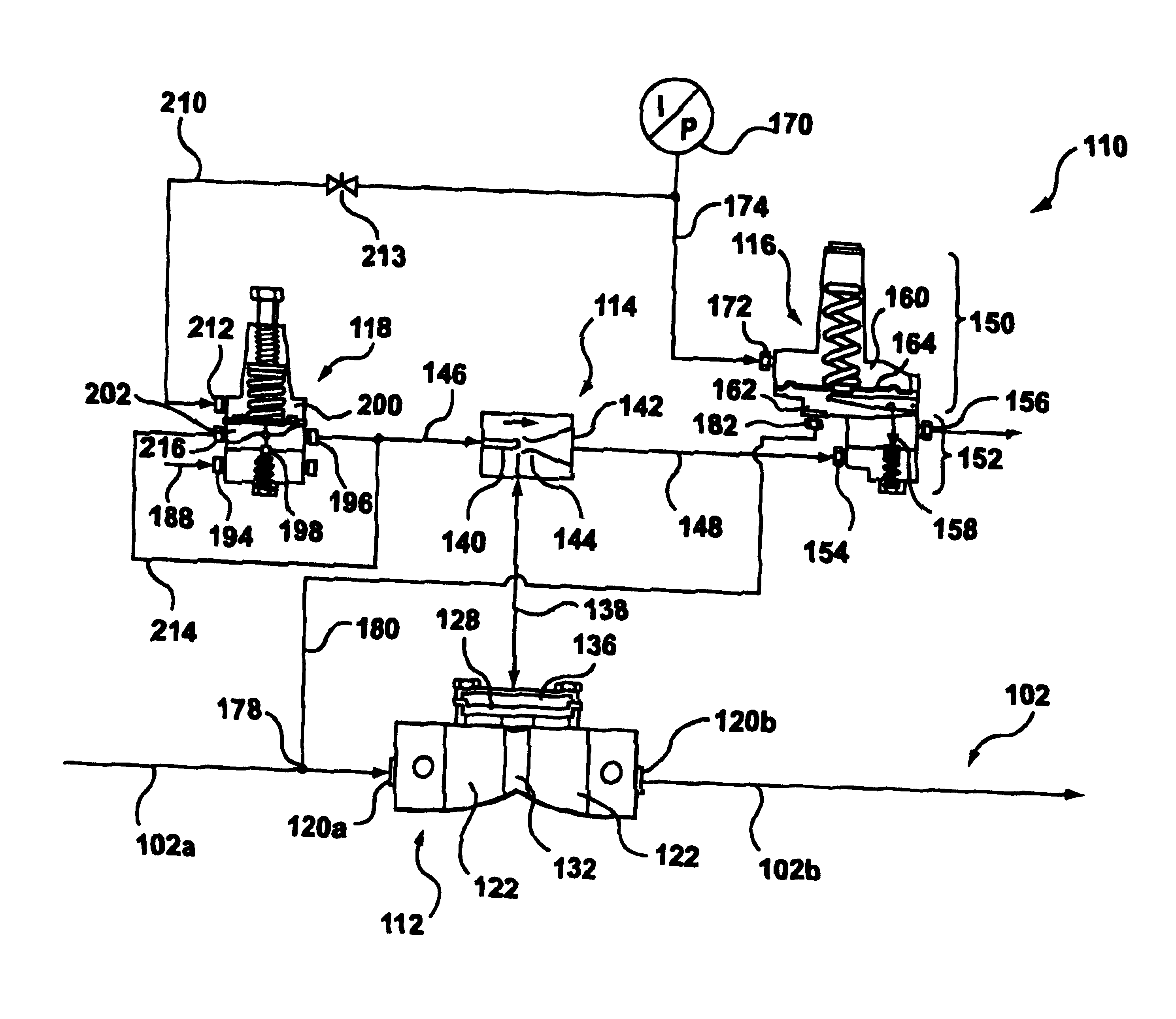
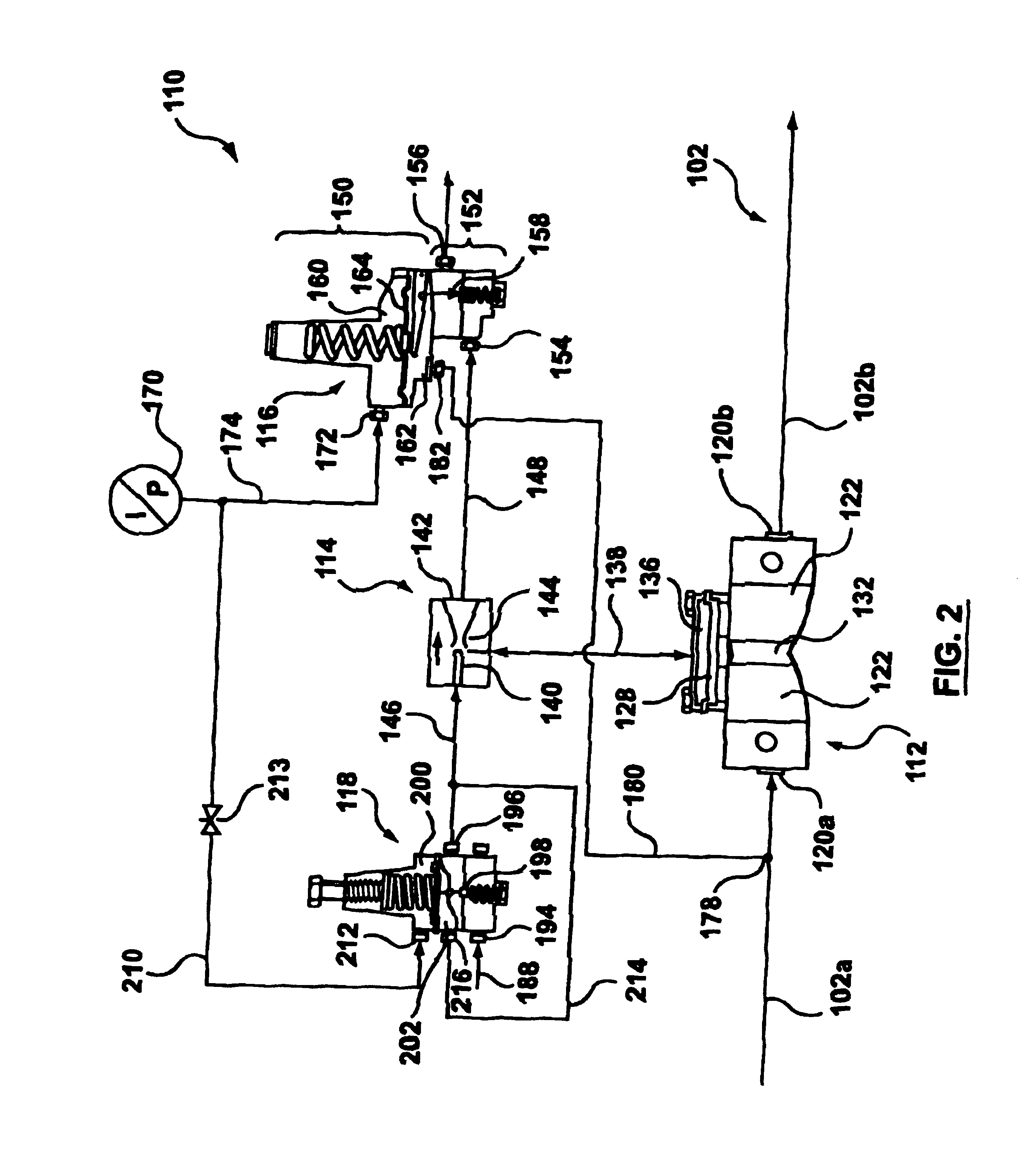
[0042]In a test run, the control pressure at inlet 170 was set at about 20 psi. The auxiliary supply stream was provided at about 100 psi. The adjustment screw 207 was adjusted so that the total force exerted on the target pressure face 205a of the diaphragm 204 was equivalent to about 25 psi. A fluid consuming device in the form of a load cell stack was disposed in the upstream fluid line 102a, between the control point and the regulator 112.

[0043]FIG. 4-8 shows test results when the present pressure control system in employed in a fuel cell system. As can be seen, although the process gas flow changes dramatically from near zero slpm to 200 slpm, the pressure of the process fluid at a certain point in the system is maintained at reasonably constant level.


PUM


Abstract

A pressure control system for controlling the pressure of a process fluid stream at a certain location having a pressure regulator disposed in the process fluid stream, through which the process fluid stream flows. A first pilot controller senses the pressure of the process fluid at the location and receives a control pressure from a control source. A second pilot controller receives the control pressure from the control source and provides added pressure. An inspirator receives the added pressure from the second pilot controller and generates a differential pressure. The differential pressure is used to control the pressure of the process fluid stream within the pressure regulator. The pressure regulator comprises a first chamber and a second chamber therein separated by a flexible element and a divider is disposed in the first chamber and operative to abut against the flexible element to divide the first chamber into separate spaces. Preferably, the pressure regulator is disposed such that the flexible element extends substantially in vertical direction and the divider extends substantially in horizontal direction.

Description

FIELD OF THE INVENTION[0001]The present invention relates generally to a pressure control system. More particularly, the present invention relates to a pressure control system for low pressure operation.BACKGROUND OF THE INVENTION[0002]In various industrial applications, it is often desirable to accurately control the pressure of a process fluid stream at a certain point in an industrial system. The process fluid can be gas, liquid, or mixture thereof. For example, in a fuel cell system or a fuel cell testing system, it is necessary to operate the fuel cell under a controlled pressure condition. A common technique is to control the pressure of a process fluid stream adjacent the inlet of the fuel cell for that process fluid stream. To this end, a pressure regulator is often utilized to control the pressure at this point.[0003]A known pressure control system comprises an unloading type flexible element pressure regulator and a piloting system. The pressure regulator is disposed in th...

Claims


Application Information

Patent Timeline
IPC IPC(8): G05D16/16G05D16/00
CPCG05D16/163G05D16/0683Y10T137/7768Y10T137/7769
Inventor LAMONT, GORDON JOHNCOMEAULT, CHADHARPER, ROGER WILLIAM
Owner HYDROGENICS CORP
Why Eureka
Try Eureka