Coating-powder spray gun

Active Publication Date: 2005-08-30
GEMA SWITZERLAND GMBH
View PDF20 Cites 6 Cited by
  • Summary
  • Abstract
  • Description
  • Claims
  • Application Information

AI Technical Summary

Benefits of technology

[0006]The objective of the present invention is to prevent or at least substantially reduce both the penetration of coating-powder particles into the front ends of chambers that are subtended by the gun housing and the entailed drawbacks.

Problems solved by technology

The latter tend to penetrating the chambers at the front end face of the gun housing.
As a result leakage currents, shorts and arcing from the high-voltage paths to the other components at lower potentials, for instance at ground, may occur, especially when the coating powder is electrically conducting or contains conducting components.

Method used


Image

  • Coating-powder spray gun
  • Coating-powder spray gun
  • Coating-powder spray gun

Examples


Embodiment Construction

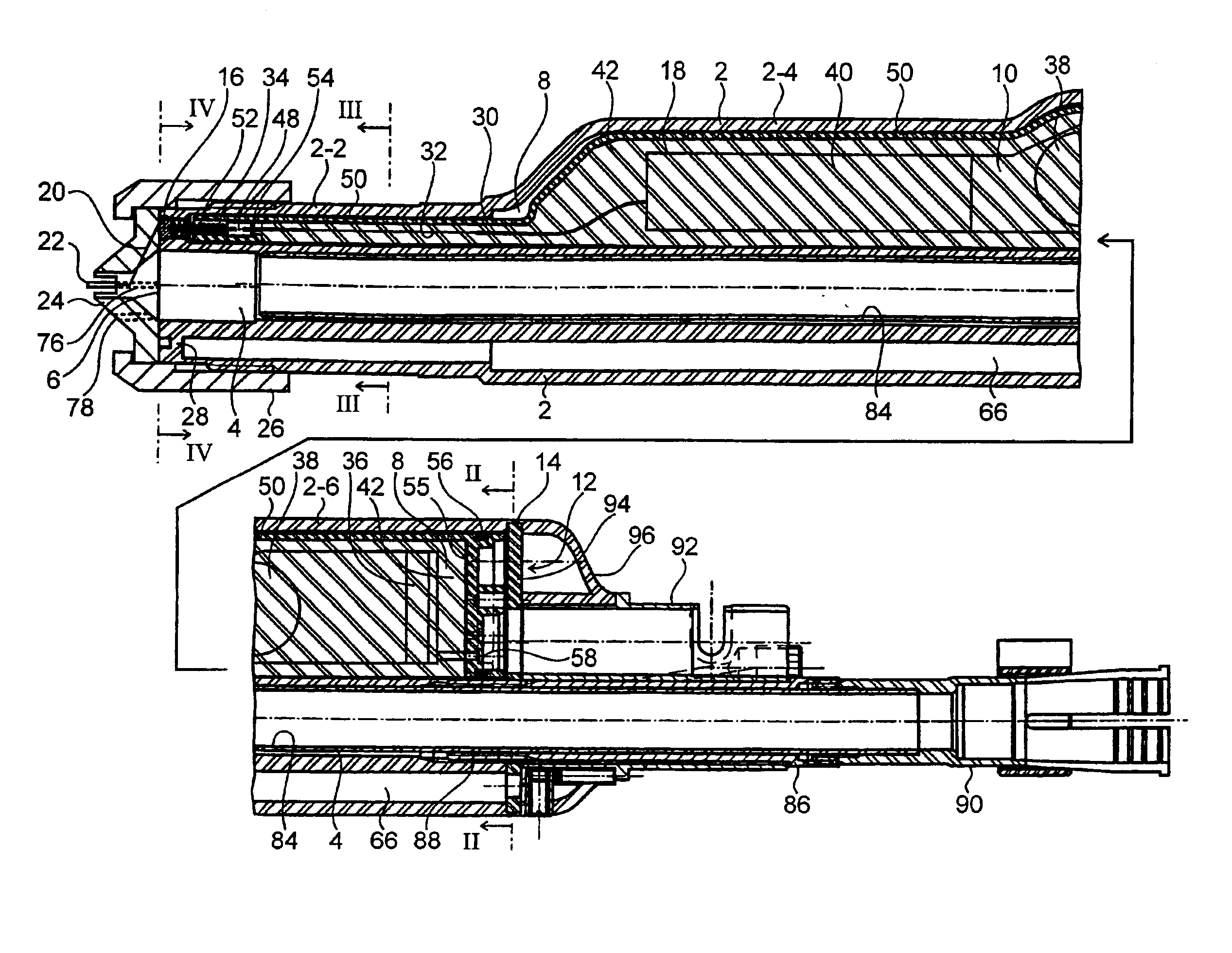
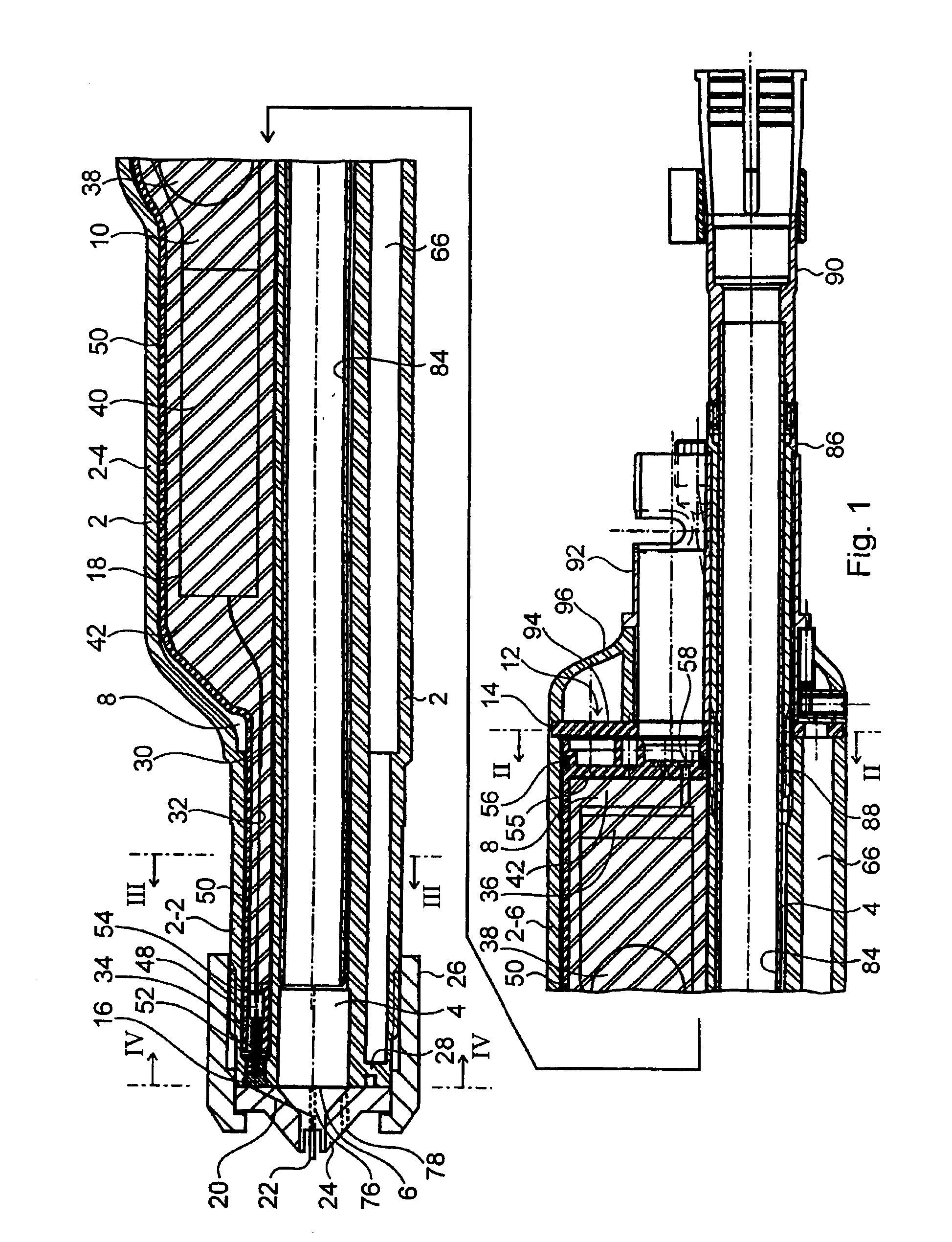
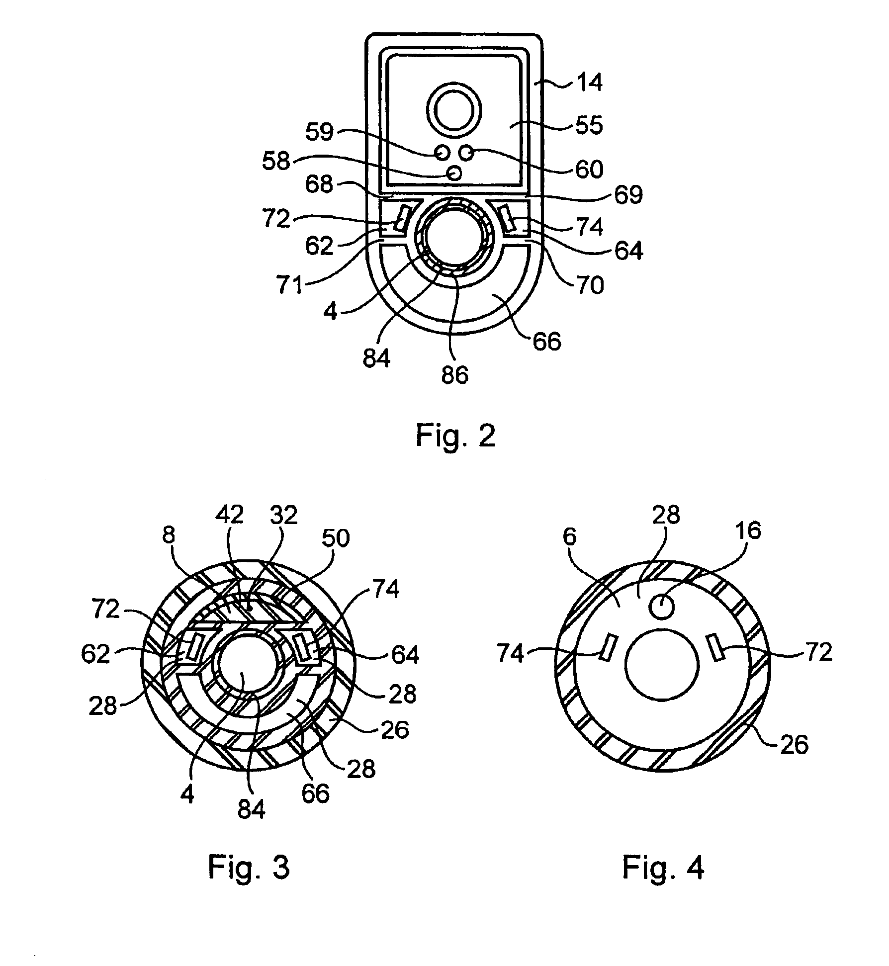
[0015]The coating-powder spray gun of the invention shown in the drawings contains an integral, electrically insulating plastic gun housing 2 preferably made by injection molding. The gun housing 2 subtends a tubular powder-feed duct 4 within a continuous block of material, said duct running in the longitudinal gun direction and issuing at a front end face 6 of the gun housing 2, further a high-voltage chamber 8 extends in the longitudinal gun direction through said housing and is fitted with an intake aperture 12 in the rear end face 14 serving to insert a high-voltage generator 10.

[0016]The high-voltage chamber 8 is pressure-hermetically sealed along its full circumference and at the front end face 6 of the gun housing 2 by this very housing. An electric jumper 16 runs through the gun housing 2 and is or may be electrically connected in conducting manner within the high-voltage chamber 8 to the high-voltage terminal 18 of the high-voltage generator 10 and outside the gun housing 2...


PUM


Abstract

A coating-powder spray gun includes a gun housing (2) of which the front end face is sealed pressure-hermetically with respect to compressed gas by a front end wall (28). A current-limiting resistor (32) and at least a portion of a high-voltage generator (10) are potted in an integral electrically insulating block. The potted block may be received in the gun housing (2).

Description

FIELD OF THE INVENTION[0001]The invention relates to a coating-powder spray gun.BACKGROUND OF THE INVENTION[0002]U.S. Pat. No. 5,759,271 (=EP 0 779 105 A1) shows a coating powder spray gun of this kind. It comprises a gun housing fitted with a tubular powder feed duct, a high-voltage chamber and further chambers all issuing openly from a rear end face of the gun housing. This document however remains silent whether the chambers are open or closed in the front end face of the gun housing. Gun housings of this kind known in practice are open at the front and at the rear. Practical designs most of the time call for a current limiting resistor between the high-voltage side of the high-voltage generator and the electrical contact in order to limit the high-voltage electrode's short-circuit current. The known powder spray gun may be affixed to a robot arm or on a support or another displaceable or immobile device.[0003]A spray gun of a similar kind is known from U.S. Pat. No. 4,993,645 an...

Claims


Application Information

Patent Timeline
IPC IPC(8): B05B5/025B05B5/053B05B5/03
CPCB05B5/032B05B5/053
Inventor MAUCHLE, FELIX
Owner GEMA SWITZERLAND GMBH
Why Eureka
Try Eureka