Fluid control device and manufacturing method for the fluid control device

Pending Publication Date: 2021-12-23
FUJIKIN INC
View PDF0 Cites 0 Cited by
  • Summary
  • Abstract
  • Description
  • Claims
  • Application Information

AI Technical Summary

Benefits of technology

[0027]According to the present invention, since a plunger for positioning each joint block is provided, each joint block is disposed in the correct position while being engaged with the support member. Therefore, since it is not necessary to adjust the position of each joint block by measuring the position with a ruler or the like, the work efficiency is improved.
[0028]Further, since each of the positioned joint blocks is temporarily fixed by the plunger, even if each of the joint blocks is not fixed with a vise or

Problems solved by technology

However, in fluid control devices of 10 mm wide, which will become the mai

Method used


Image

  • Fluid control device and manufacturing method for the fluid control device
  • Fluid control device and manufacturing method for the fluid control device
  • Fluid control device and manufacturing method for the fluid control device

Examples


Example

First Embodiment

[0047]In this embodiment, a plunger is provided at a position corresponding to each joint block to fix the position of each joint block. A plurality of screw holes for screwing the plunger may be provided in the rail member and select a screw hole to which the plunger should be screwed according to the position of the joint block.

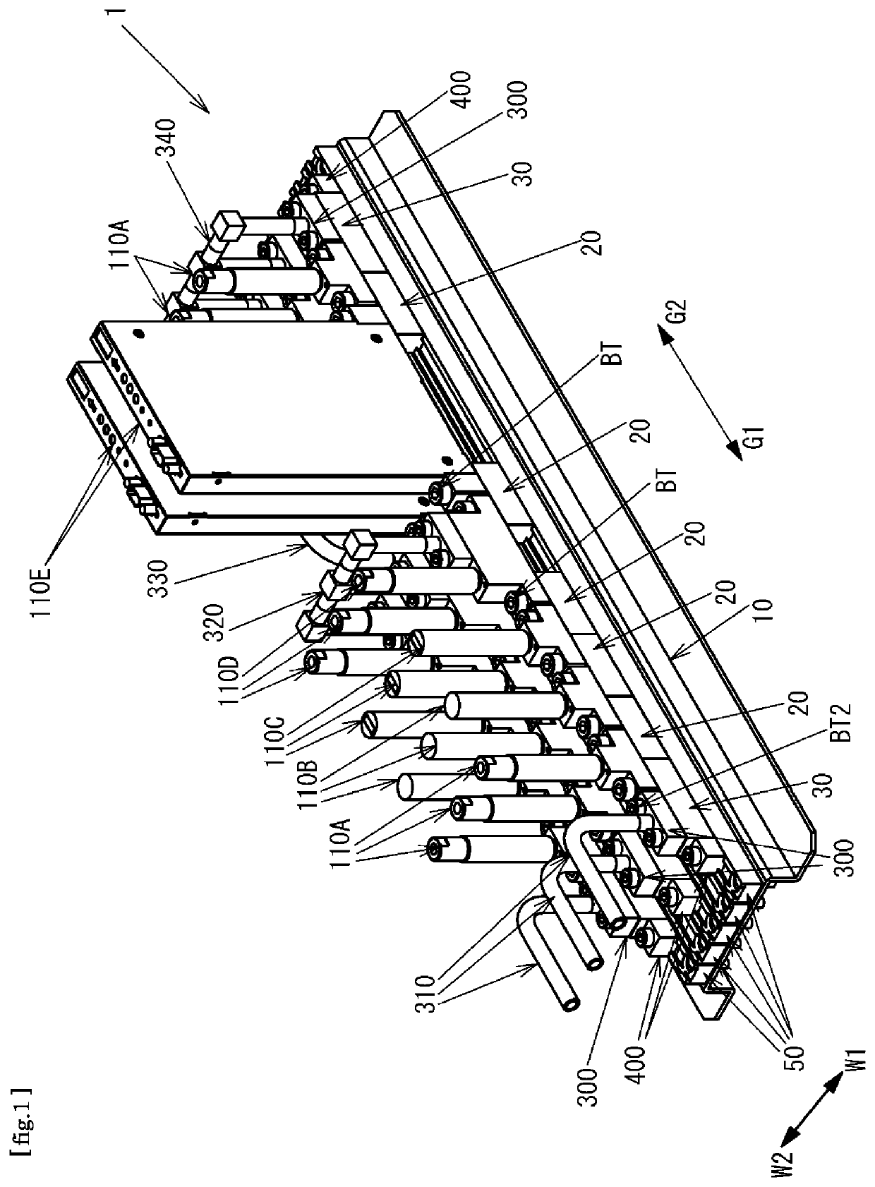
[0048]As shown in FIG. 1, in the fluid control device 1, on a metallic base plate 10, there are provided five rail members 50 as support members extending in the longitudinal direction G1, G2 and arranged along the width direction W1, W2. Note that W1 represents the front side, W2 represents the back side, G1 represents the upstream side, and G2 represents the downstream side. Of the five rail members 50, various members are installed only in the rail members 50 at both ends and the center, and nothing is installed in the second and fourth rail members 50, resulting in an empty state. However, various members can be additionally installed on...

Example

Second Embodiment

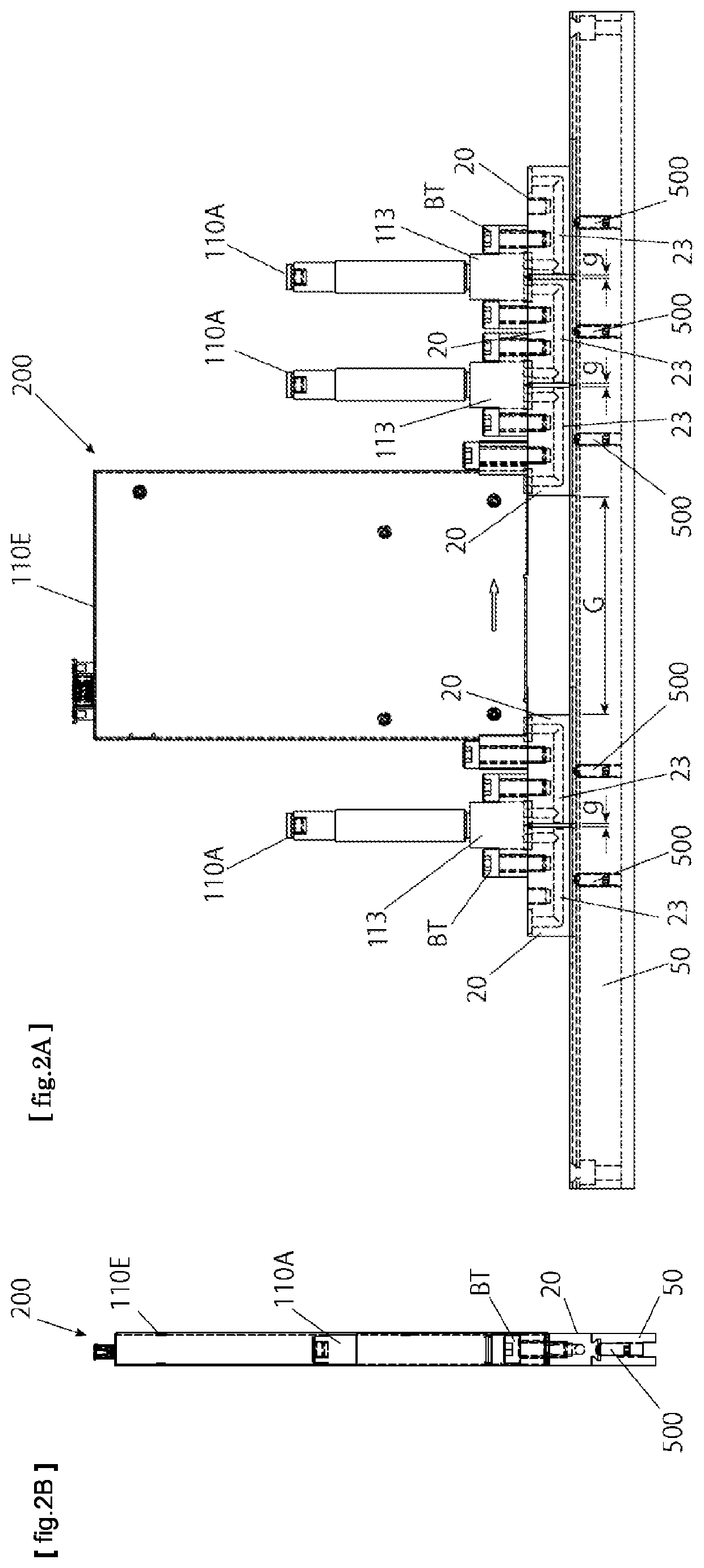
[0094]In this embodiment, only one plunger is provided to each rail member 50 (support member), and all the joint blocks are arranged in contact with each other and integrally positioned.

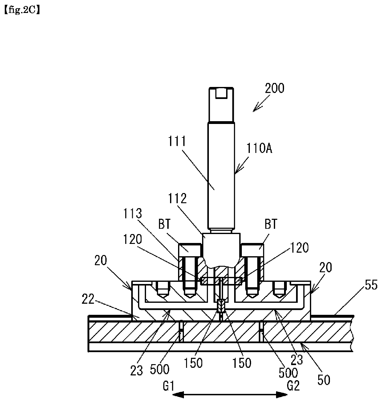
[0095]FIG. 8 is a front view showing an assembly 200 constituting one line of the fluid control device of the present embodiment. In the present embodiment, the plunger 500 is provided only one, and the plunger 500 is engaged with a recess 27 of the leftmost (upstream side) joint block 20 among joint blocks 20 and 30 engaged with the rail member 50, to position the joint block 20. All other joint blocks 20 and 30 are arranged in contact with each other starting from the leftmost joint block 20.

[0096]In the present embodiment, not only short joint blocks 20 but also a long joint block 30 are arranged so that the joint blocks 20 and 30 are in contact with each other even below a mass flow controller 110E which is a large fluid device. In order to realize correct positioning by mutual ...


PUM


Abstract

A fluid control device comprises includes: a joint block defining a fluid flow path open to an upper surface thereof, and which has an engaging portion on the bottom surface side thereof; a support member having a guide portion which restrains the joint block on the upper surface while permitting the joint block to move in longitudinal direction; and a fluid device fixed to the upper surface of the joint block. The support member is provided with at least one plunger such that the tip end portion protrudes from the upper surface of the support member. A recess is provided in the bottom surface of the joint block, and the recess engages with the tip end portion of the plunger to set the position of the joint block in the longitudinal direction.

Description

TECHNICAL FIELD[0001]The present invention relates to a fluid control device in which fluid devices are integrated and a manufacturing method for the fluid control device.BACKGROUND ART[0002]As fluid control devices used for supplying various process gases to a chamber or the like of a semiconductor manufacturing apparatus or the like, fluid control devices are widely used, in which a plurality of fluid devices is arranged from upstream to downstream.[0003]In the field of the fluid control device as described above, high responsiveness of process gas supply control is required, and for this purpose, fluid control device should be miniaturized and integrated as much as possible and installed closer to a chamber to which fluids are supplied.[0004]Further, along with increase in the size of the object to be processed such as increase in the diameter of semiconductor wafers, it is necessary to increase the supply flow rate of the fluid supplied from the fluid control device into the cha...

Claims


Application Information

Patent Timeline
IPC IPC(8): F16K27/00F16K27/02
CPCF16K27/003F16K27/0245F16K31/50H01L21/67017F15B13/0825
Inventor AIKAWA, KENJINAKATA, TOMOHIROINADA, TOSHIYUKIHARADA, AKIHIROMATSUDA, TAKAHIROSHINOHARA, TSUTOMU
Owner FUJIKIN INC
Why Eureka
Try Eureka