Compressor casing with passive tip clearance control and endwall ovalization control

a technology of endwall ovalization control and compressor casing, which is applied in the direction of machines/engines, stators, liquid fuel engines, etc., can solve the problems of serious affecting compressor efficiency and stall margin

Inactive Publication Date: 2005-08-30
ALLISON ADVANCED DEVMENT
View PDF19 Cites 77 Cited by
  • Summary
  • Abstract
  • Description
  • Claims
  • Application Information

AI Technical Summary

Problems solved by technology

Tip clearance levels above this range can seriously affect compressor efficiency and stall margin.
As a result of these limitations, the majority of current production engines avoid single wall horizontally split compressor cases.

Method used


Image

  • Compressor casing with passive tip clearance control and endwall ovalization control
  • Compressor casing with passive tip clearance control and endwall ovalization control
  • Compressor casing with passive tip clearance control and endwall ovalization control

Examples


Embodiment Construction

[0022]For purposes of promoting an understanding of the principles of the invention, reference will now be made to the embodiments illustrated in the drawings and specific language will be used to describe the same. It will nevertheless be understood that no limitation of the scope of the invention is thereby intended, such alterations and further modifications in the illustrated device, and such further applications of the principles of the invention as illustrated therein being contemplated as would normally occur to one skilled in the art to which the invention relates.

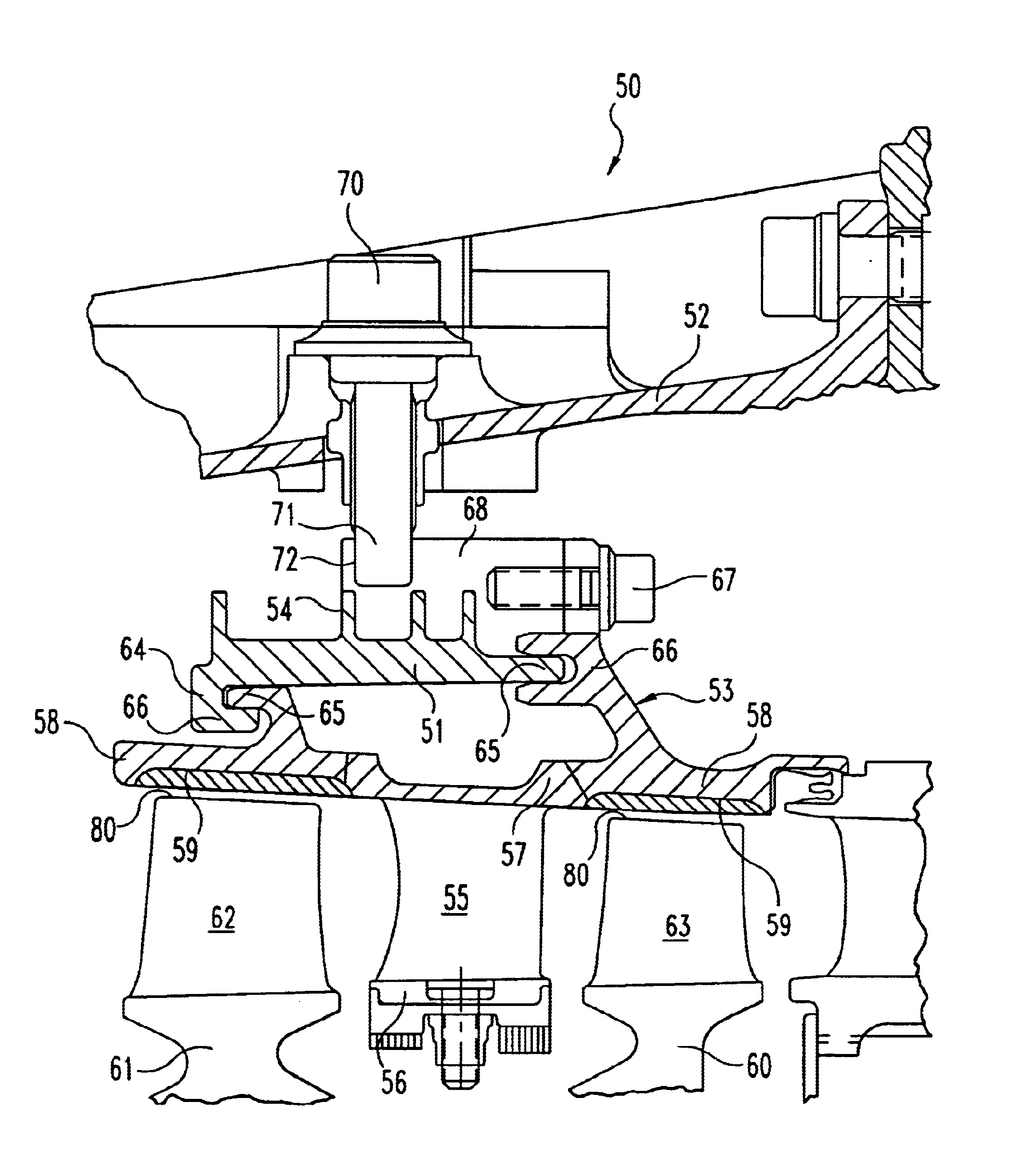
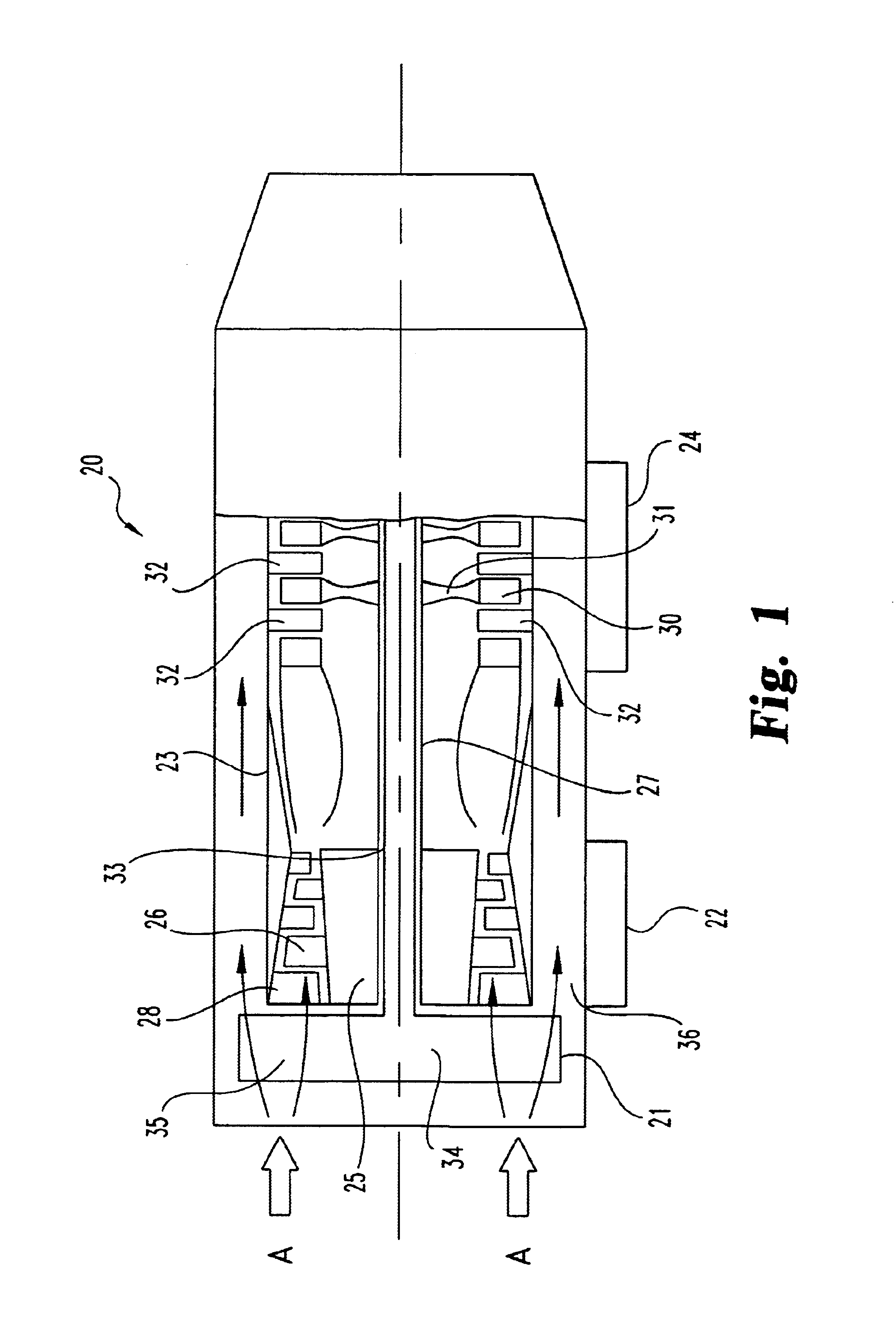
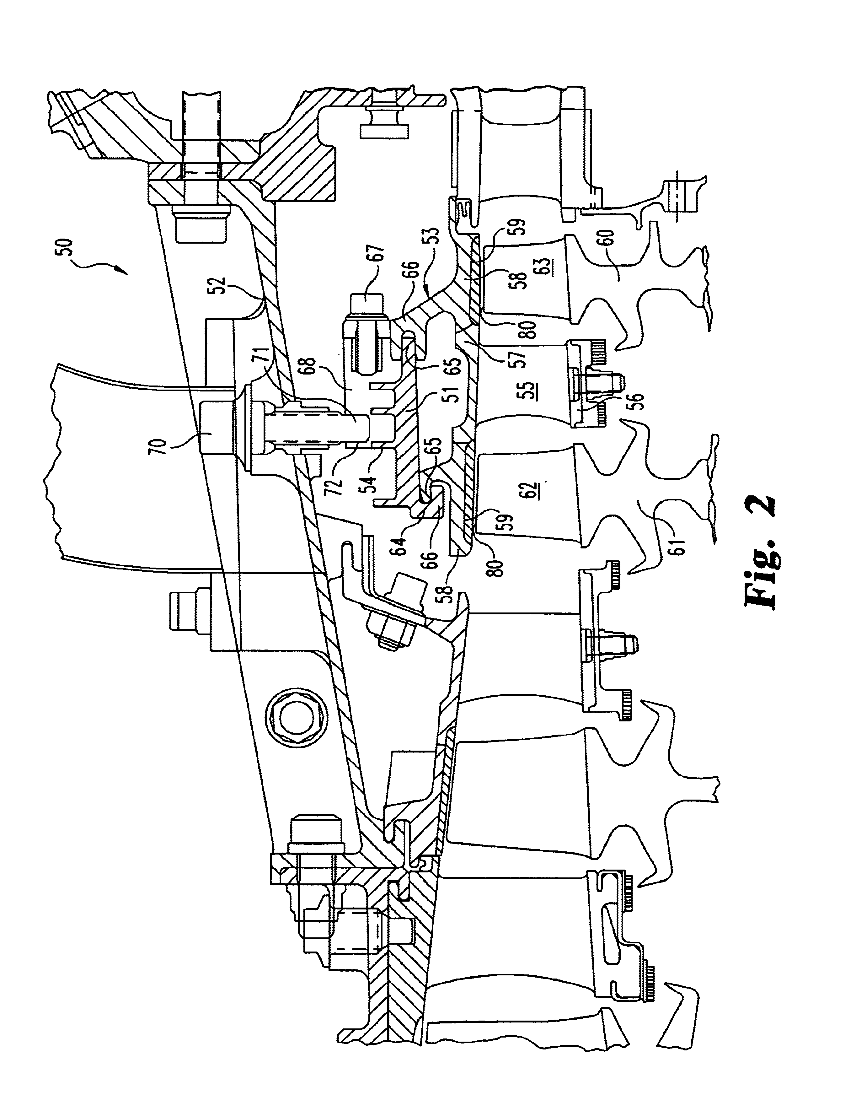
[0023]Referring to FIG. 1, there is illustrated a gas turbine engine 20 which includes a fan section 21, a compressor section 22, a combustor section 23, and a turbine section 24 that are integrated together to produce an aircraft flight propulsion engine. This type of gas turbine engine is generally referred to as a turbo-fan. One alternate form of a gas turbine engine includes a compressor, a combustor, and a tur...


PUM


Abstract

A passive clearance control system for a gas turbine engine component. The system provides a blade shroud that is isolated from the component case and can move radially to maintain blade clearance. A plurality of vane sectors define a stator ring including a blade shroud. The stator ring and the control ring are coupled together and mounted within the component by a plurality of radial extending mounting members.

Description

CROSS-REFERENCE TO RELATED APPLICATION[0001]The present application claims the benefit of U.S. Provisional Patent Application No. 60 / 386,469 filed Jun. 5, 2002, which is incorporated herein by reference.BACKGROUND OF THE INVENTION[0002]The present invention relates generally to gas turbine engine compressor case designs. More particularly, one form of the present invention relates to a compressor case including a mechanical arrangement that provides both passive tip clearance control and endwall ovalization control. Although the present invention was developed for application in a gas turbine engine compressor, applications in other components of the gas turbine engine are contemplated herein.[0003]Tip clearance has been shown to be a significant factor influencing compressor performance. Current design trends attempt to control tip clearance to span ratios on the order of about one to two percent at the rear of the compressor. Tip clearance levels above this range can seriously aff...

Claims


Application Information

Patent Timeline
Patent Type & Authority Patents(United States)
IPC IPC(8): F01D11/00F01D11/08F01D5/20F01D5/14F01D11/16F01D11/02
CPCF01D11/025F01D11/16Y02T50/672Y02T50/60
Inventor RESS, JR., ROBERT ANTHONYKING, BRIAN
Owner ALLISON ADVANCED DEVMENT
Why Eureka
Try Eureka