Spontaneous inflation inhibitor for inflatable prosthesis

a prosthesis and inhibitor technology, applied in the direction of pressure relieving devices on sealing faces, positive displacement liquid engines, liquid fuel engines, etc., can solve the problem that the pressure generated by compressing the pump bulb will far exceed the level of overpressur

Inactive Publication Date: 2005-08-30
BOSTON SCI SCIMED INC
View PDF65 Cites 44 Cited by
  • Summary
  • Abstract
  • Description
  • Claims
  • Application Information

AI Technical Summary

Benefits of technology

[0011]The present invention includes a penile pump having a dual poppet arrangement wherein the poppets act as check valves or flow valves. Each poppet is spring-biased against a valve seat, and under normal circumstances, only allows positive fluid flow when a pump bulb is engaged. To prevent spontaneous inflation when an overpressurization occurs in the reservoir, the same reservoir pressure is utilized to seal the fluid output against itself or to seal one or both of the poppets against the valve seat. Thus, the fluid is prevented from reaching the cylinders and creating a spontaneous inflation. When the movement or activity generating the overpressure in the reservoir is released, the system will return to an equilibrium and allow normal operation. Even if overpressurization of the reservoir is occurring, the pressure generated by compressing the pump bulb will far exceed the level of overpressure. Thus, the poppets will open in the normal way, allowing fluid to flow to the cylinders.

Problems solved by technology

Even if overpressurization of the reservoir is occurring, the pressure generated by compressing the pump bulb will far exceed the level of overpressure.

Method used


Image

  • Spontaneous inflation inhibitor for inflatable prosthesis
  • Spontaneous inflation inhibitor for inflatable prosthesis
  • Spontaneous inflation inhibitor for inflatable prosthesis

Examples


first embodiment

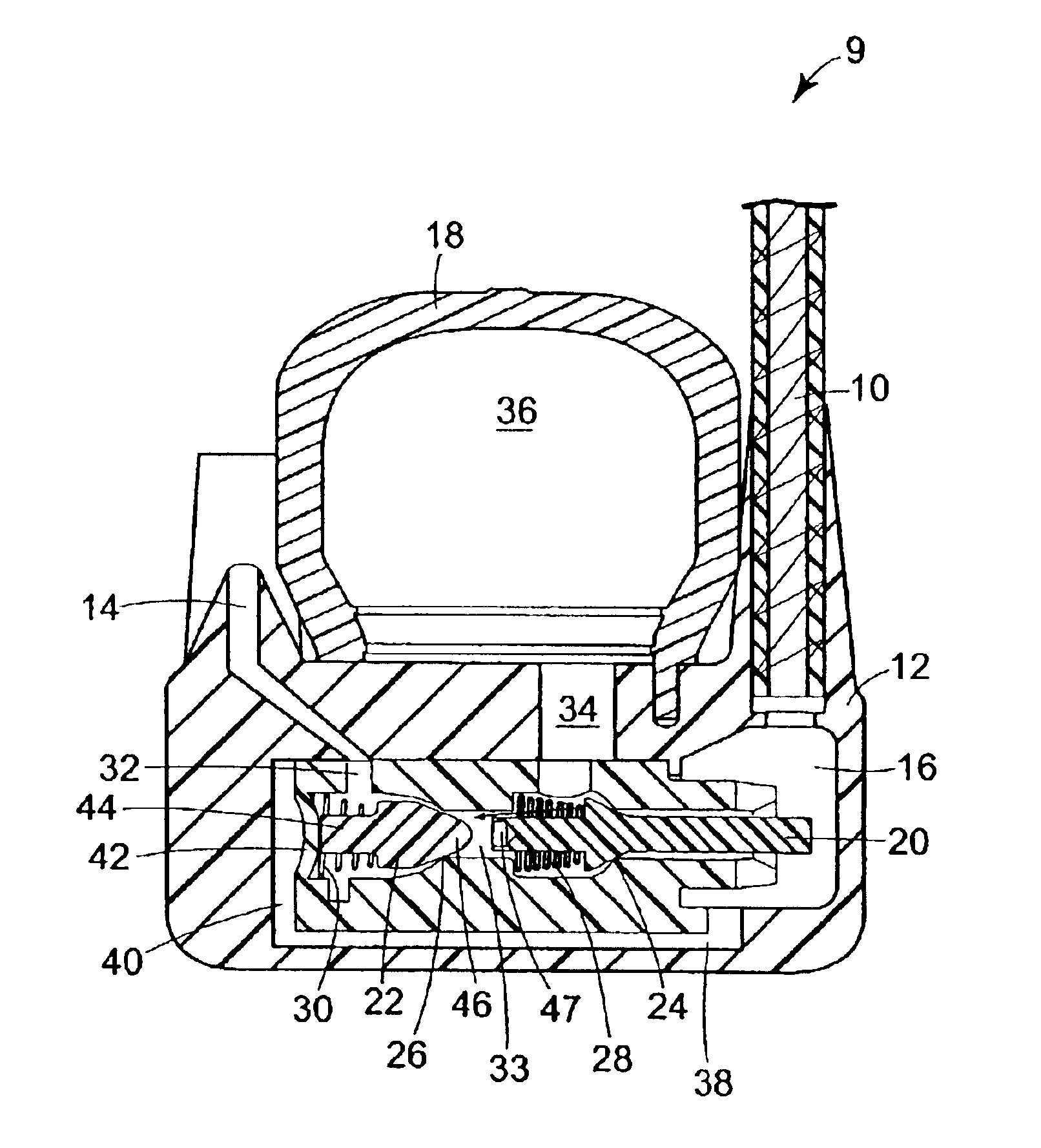
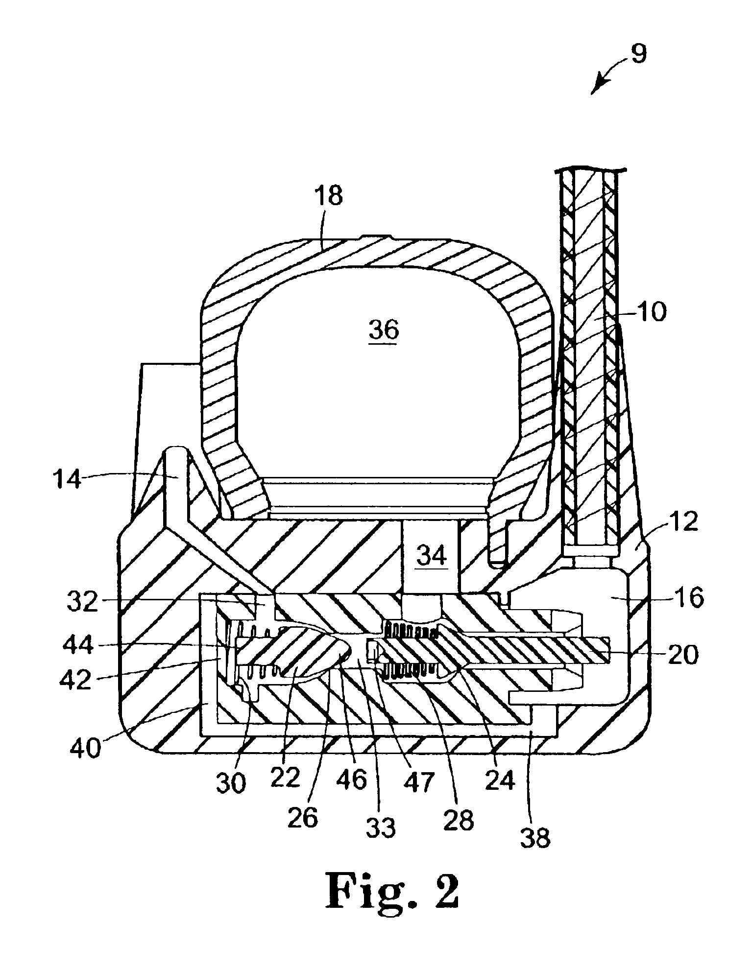
[0047]Referring to FIG. 2, the present invention is shown and described. In summary, an overpressure tolerant pump assembly 9 is provided and including a bypass passageway 38 is added to the system which couples input chamber 16 to an expansion chamber 40. The expansion chamber 40 is provided adjacent to the rear end 44 of cylinder poppet 22. The relatively thin portion of housing 12 that exists between common passageway 33 and expansion chamber 40 forms an abutting wall 42. Abutting wall 42 is relatively flexible and operates very similarly to a flexible diaphragm. Importantly, the planar surface area of abutting wall 42 is greater than the area of nose 46 of cylinder poppet 22 (wherein the nose 46 is that portion of cylinder poppet 22 that would be exposed to overpressure generated by the reservoir when the cylinder poppet 22 is seated against the valve seat 26). This “nose” area is approximately equal to the cross sectional area of the common passageway 33, at a point between the...

second embodiment

[0052]Referring to FIG. 4, the present invention is illustrated. Once again a bypass passageway 38 is provided. Bypass passageway 38 is fluidly coupled at one end to the input chamber 16. An expansion chamber 49 and a junction chamber 48 are provided at the opposite end of bypass passageway 38. Cylinder poppet output 32 (which is coupled with common passageway 33) is fluidly coupled to junction chamber 48. Finally, fluid output 14 is also fluidly coupled to junction chamber 48. Disposed between junction chamber 48 and expansion chamber 49 is a flexible diaphragm 50. During normal operation, flexible diaphragm is in the state represented by dashed lines. That is, flexible diaphragm 50 is flush against bypass passageway 38. When manually actuated, the pressurized fluid from the pump bulb 18 is forced through common passageway 33, bypassing cylinder poppet 22 and exiting through cylinder poppet output 32 into fluid output 14, unhindered by flexible diaphragm 50.

[0053]During an overpres...

third embodiment

[0057]Referring to FIG. 6, the present invention is illustrated. Bypass passageway 38 fluidly couples input chamber 16 to a compression chamber 52. Compression chamber 52 surrounds a portion of fluid output 14. If not already sufficiently flexible, the portion of the fluid output 14 within compression chamber 52 can be formed from a flexible, easily compressible material. During an overpressure situation, compressed fluid from the reservoir is forced through fluid input 10 and into input chamber 16. The compressed fluid flows through bypass passageway 38 and into compression chamber 52 where it compresses compressible tube 54 (which is that section of fluid output 14 within compression chamber 52). The amount of surface area on the outer surface of compressible tube 54 will necessarily be greater than the surface area within the compressible tube 54. As such, the force generated will be greater in a direction compressing compressible tube 54 than a counterforce trying to expand it. ...


PUM


Abstract

A pump assembly for a penile implant is provided having a mechanism which prevents spontaneous inflation of the cylinders implanted within the user. The preventative mechanism uses overpressure generated by the reservoir during unintentional compression to effectively seal the pump assembly from unintended fluid flow. The prevention mechanism itself creates all necessary forces to prevent the undesired fluid flow to the cylinders. This is accomplished by incorporating appropriate mechanisms within the pump itself.

Description

CROSS REFERENCE TO RELATED APPLICATIONS[0001]This application is a divisional of U.S. patent application Ser. No. 09 / 749,256, filed Dec. 27, 2000, now U.S. Pat. No. 6,533,719.BACKGROUND OF THE INVENTION[0002]This invention generally relates to a pump for inflating a prostheses and more particularly to a pump and valve assembly including a diaphragm which inhibits spontaneous inflation of the prosthesis.[0003]One common treatment for male erectile dysfunction is the implantation of a penile prosthesis. Such a prosthesis typically includes a pair of inflatable cylinders which are fluidly connected to a fluid reservoir via a pump and valve assembly. The two cylinders are normally implanted into the corpus cavernosae of the user and the reservoir is typically implanted in the user's abdomen. The pump assembly is implanted in the scrotum. During use, the user actuates the pump and fluid (typically liquid) is transferred from the reservoir through the pump and into the cylinders. This res...

Claims


Application Information

Patent Timeline
Patent Type & Authority Patents(United States)
IPC IPC(8): A61F2/26A61F5/00
CPCA61F2/26Y10T137/7842Y10T137/7838Y10T137/1842Y10T137/7777Y10T137/785F16K2200/3053F16K2200/204F16K15/066
Inventor KUYAVA, CHARLES C.WESTRUM, JR., JOHN W.CLARK, DAVID W.
Owner BOSTON SCI SCIMED INC
Why Eureka
Try Eureka