Method and device for lateral adjustment of image

a technology of lateral adjustment and image, applied in the field of optical components, can solve the problems of inability to use software to achieve image stabilization, inability to use software, and inability to achieve the effect of lateral adjustment,

Active Publication Date: 2005-08-30
NOKIA TECHNOLOGLES OY
View PDF5 Cites 61 Cited by
  • Summary
  • Abstract
  • Description
  • Claims
  • Application Information

AI Technical Summary

Benefits of technology

[0012]applying an electric field on the deformable lens for causing a change in the optical axis so as

Problems solved by technology

The mechanical movement of the lens component involves complex and expensive mechanical structures.
In a mobile phone with limited image capability, the prior art method for image stabilization using softwa

Method used


Image

  • Method and device for lateral adjustment of image
  • Method and device for lateral adjustment of image
  • Method and device for lateral adjustment of image

Examples


Embodiment Construction

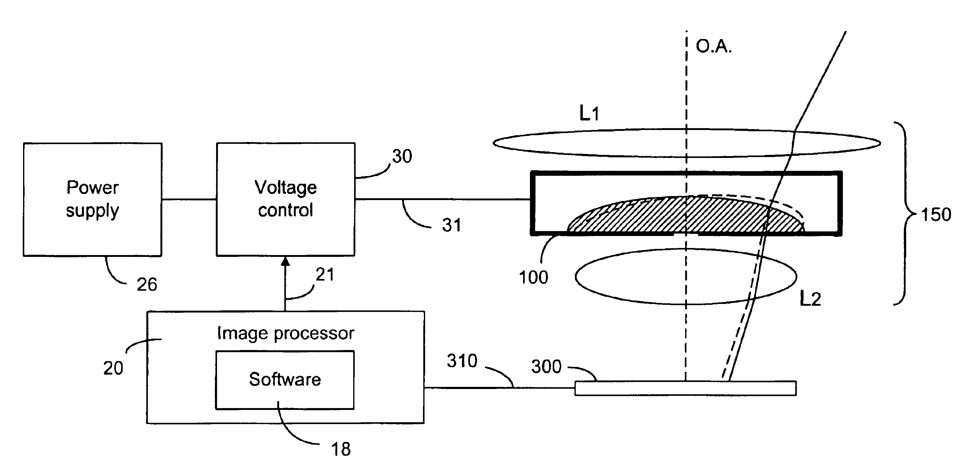
[0073]The present invention uses a liquid lens for image shifting. A voltage control system is used to deform the liquid lens in an asymmetrical way. The present invention uses electrowetting (EW) technology to provide the required liquid lens. In EW technology, a droplet of liquid is placed on a substrate to function as a lens. The contact angle of the droplet is usually a function of the surface tension of the liquid under the influence of the surface properties of the substrate. When an electric field is applied to the liquid droplet, the electric field modifies the surface tension at the liquid-solid interface, causing a change in the contact angle (see FIG. 3, contact angle is changed from θ to θ′). The change in the contact angle causes a change in the surface curvature of the droplet.

[0074]EW technology is known in the art. Kroupenkine et al. (EP 1 271 218 A1) discloses disposing a liquid droplet on a substrate as a liquid lens having a focal length and applying a voltage on ...


PUM


Abstract

A liquid lens, according to the electrowetting principle, is used in an imaging system to affect the optical axis of the imaging system. In particular, a seal compartment having a first side and an opposing second side is used to dispose a liquid lens on the first side. A plurality of electrode areas are disposed adjacent to the first side and a common electrode is disposed adjacent to the second side. In order to compensate for undesirable image shifting due to hand motion, different voltage levels are applied to the plurality of electrode areas so that the electric field applied on the liquid lens is non-uniform, causing deformation of the liquid lens. The voltage levels are determined such that the shift in the optical axis due to the deformation of the liquid lens substantially cancels out the motion-induced image shift.

Description

[0001]This patent application is based on and claims priority to U.S. Provisional Patent Application Ser. No. 60 / 455,151, filed Mar. 17, 2003.CROSS REFERENCE TO RELATED APPLICATIONS[0002]This patent application is related to U.S. patent application Ser. No. 10 / 803,545, assigned to the assignee of the instant application, and filed even date herewith.FIELD OF THE INVENTION[0003]The present invention relates generally to an optical component for forming an image in an imaging device and, more specifically, to the stabilization of the image, which is caused to shift laterally on the image plane by hand motion or other vibrations.BACKGROUND OF THE INVENTION[0004]When taking a still image, a series of still images or video images using an imaging device, such as a camera, a camcorder, a video recorder, a mobile phone or the like, the user's hand may shake, causing the image formed on the image plane to shift laterally. The shift could blur the image. The shift can be caused by the tiltin...

Claims


Application Information

Patent Timeline
IPC IPC(8): H01J40/14H01J3/00G21K5/10H01J5/02H01J5/16H01J40/00H01J3/14H01L27/00G02B3/12G02B3/14G02B27/64H04N5/232
CPCG02B3/12G02B3/14G02B26/005G02B27/646H04N5/2254H04N5/23248H04N5/23287G03B5/02G03B21/147H04N2007/145H04N23/68H04N23/687
Inventor VIINIKANOJA, JARKKO
Owner NOKIA TECHNOLOGLES OY
Why Eureka
Try Eureka