Apparatus for manipulating magnetic fields

a magnetic field and apparatus technology, applied in the field of electromagnets, can solve the problems of damage to the substrate, no of the foregoing techniques for producing magnetic fields inside the reactor vessel provides a perfect solution for meri

Inactive Publication Date: 2005-08-30
OSTER EUGENE L
View PDF6 Cites 21 Cited by
  • Summary
  • Abstract
  • Description
  • Claims
  • Application Information

AI Technical Summary

Problems solved by technology

Though the electromagnetic coils on the sides of the vessel permit rotation of the magnetic field, the lack of uniformity of the magnetic field both causes irregularities in the plasma and these in turn may lead to damage in the substrate.
None of the foregoing techniques for producing magnetic fields inside a reactor vessel provides a perfect solution for MERIE.

Method used


Image

  • Apparatus for manipulating magnetic fields
  • Apparatus for manipulating magnetic fields
  • Apparatus for manipulating magnetic fields

Examples


Embodiment Construction

[0028]The following Detailed Description will first present an overview of the invention, will then disclose a preferred embodiment of an electromagnet that may be used in the invention, and will finally disclose how existing reactor vessels may be retrofitted with the invention.

Overview of the Invention

[0029]The following overview will first describe a type of magnet used in the invention in which the magnetic field is produced using opposed magnetic elements, will then describe how magnetic fields may be made by arranging such magnets above each other, and will finally describe a particularly useful arrangement of such magnets which is termed herein a Helmholtz core arrangement.

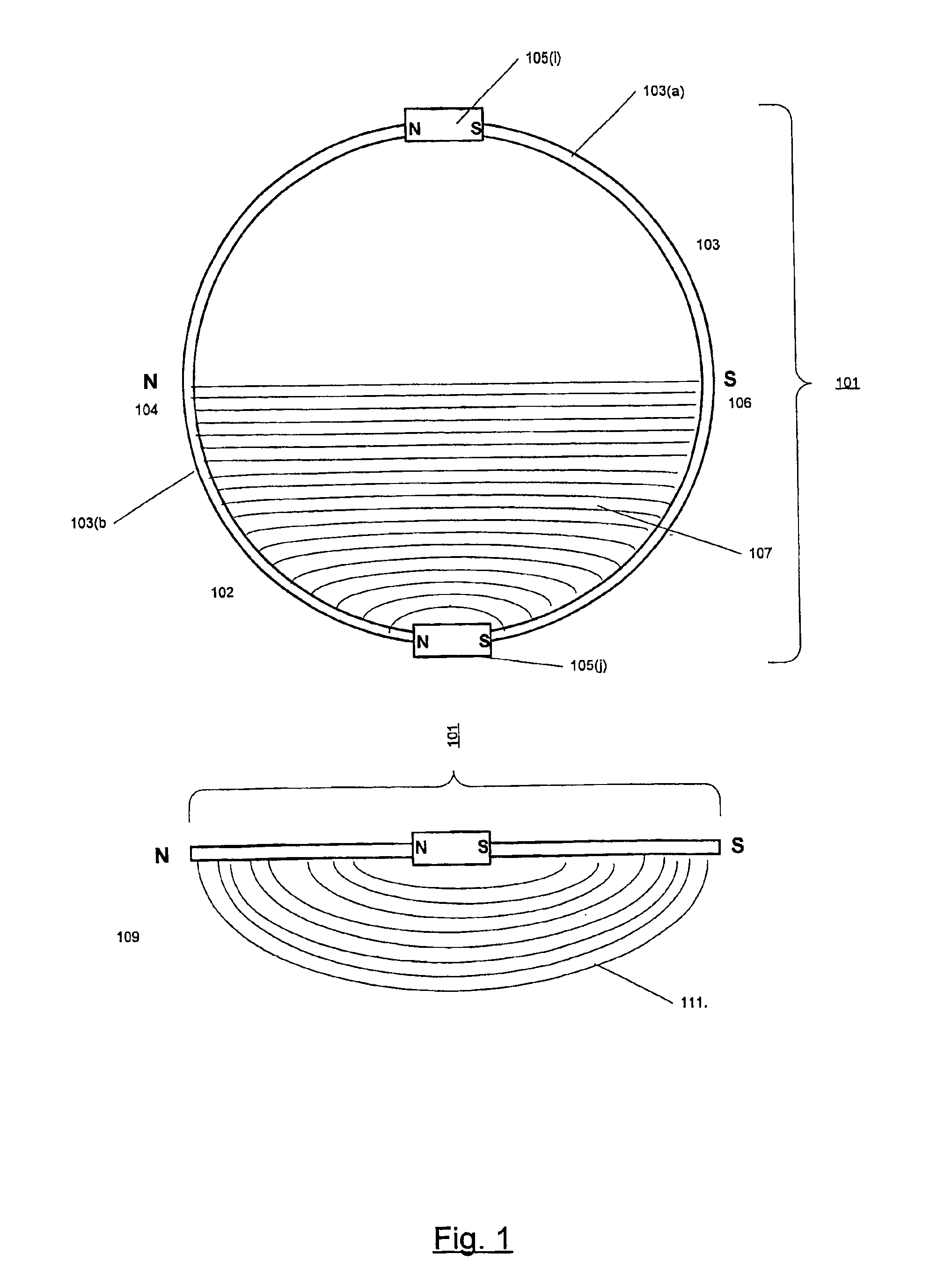
A Magnet in Which the Magnetic Field is Produced by Opposing Magnetic Elements: FIG. 1

[0030]FIG. 1 shows a magnet 101 in which two active magnetic elements 105(i) and (j) of equal strength are connected by a circular core 103 of a magnetically permeable material. The magnetic elements may be either electrom...


PUM

PropertyMeasurementUnit
distanceaaaaaaaaaa
magnetic fieldaaaaaaaaaa
magnetic fieldsaaaaaaaaaa

Abstract

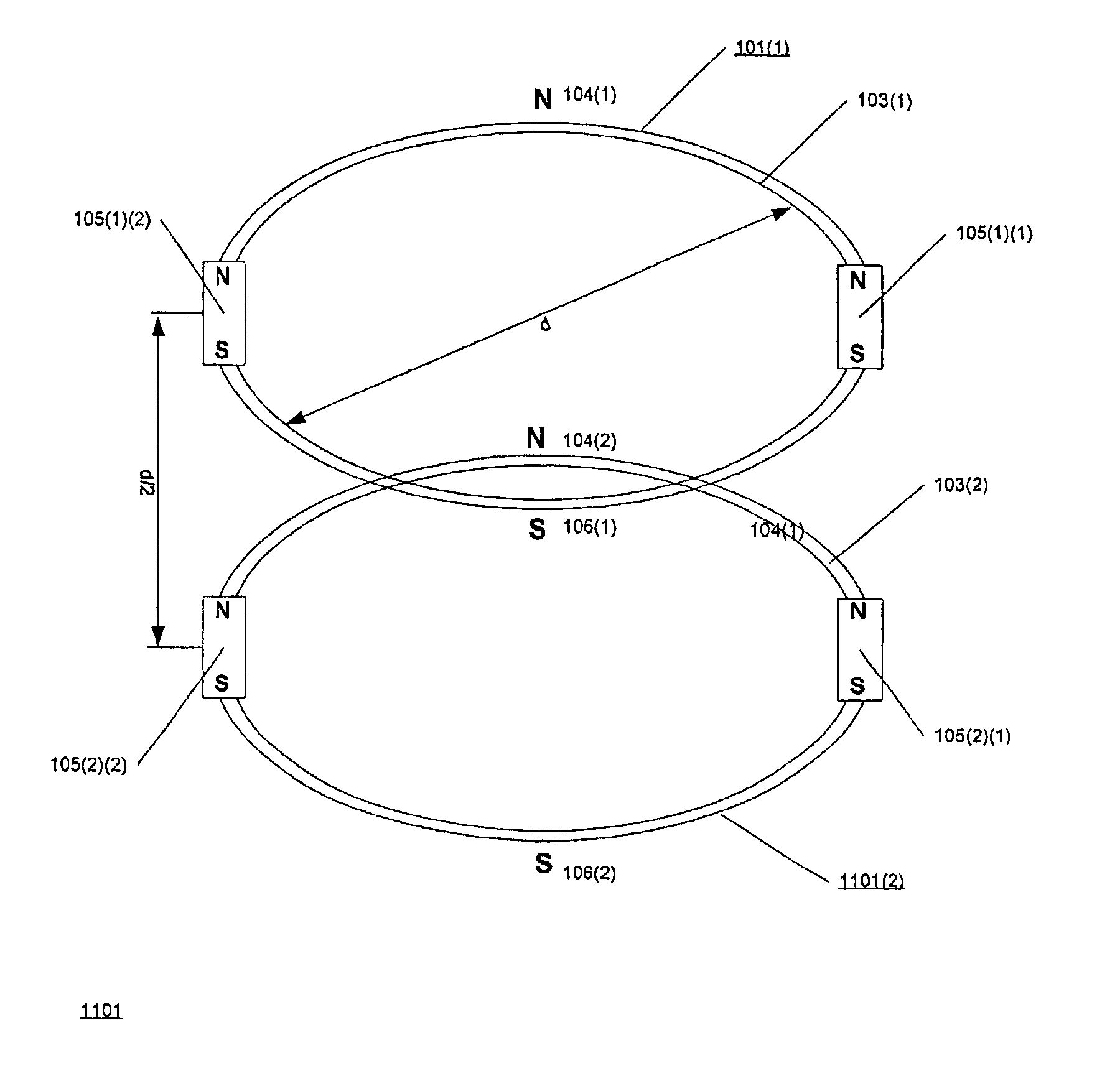
Techniques for producing and manipulating magnetic fields. The techniques employ the mutual repulsion of magnetic fields to create uniform magnetic fields and to manipulate the uniform magnetic fields. The uniform magnetic field is created between two planar magnets. The planar magnets have cores which describe a closed curve. Like poles of the electromagnets are connected by the cores. When the electromagnets are activated, repulsion between the magnetic fields generated by the electromagnets creates a magnetic field which extends above and below the planes of the planar magnets. If the planar magnets are positioned parallel to each other and aligned so that the magnetic fields generated by the planar magnets repel each other in the space between the planar magnets, the repulsion between the fields generates a resultant field. When the distance between the planar magnets is approximately ½ the diameter of the closed curve, the resultant field is uniform over a considerable volume of the space between the planar magnets. The uniform field may be manipulated by varying the magnitude and direction of the current provided to the electromagnets. Depending on the number and positions of the electromagnets and how power is supplied to them, the uniform field may be rotated, tilted in the horizontal and / or vertical planes, warped in the horizontal and / or vertical planes, and given gradients in the horizontal and / or vertical planes. The planar magnets may be fitted around the chambers of reactors such as those used for MERIE and the uniform field may be used to manipulate the plasma in the reactor chamber.

Description

CROSS REFERENCES TO RELATED APPLICATIONS[0001]The present patent application claims priority from U.S. provisional patent application 60 / 409,323, Eugene L. Oster, “Any Angle” uniform field etch plasma magnet array, filed Sep. 9, 2002 and from U.S. provisional patent application 60 / 486,676, Eugene L. Oster, Improved “any angle” uniform field etch plasma magnet array, filed Jul. 11, 2003, and incorporates U.S. Pat. No. 6,015,476, Schlueter, et al., Plasma reactor magnet with independently-controllable parallel axial current-carrying elements, issued Jan. 18, 2000, by reference for all purposes.BACKGROUND OF THE INVENTION[0002]1. Field of the Invention[0003]The invention relates to electromagnets generally and more specifically to electromagnets used to manipulate magnetic fields in enclosed vessels.[0004]2. Description of Related Art[0005]Magnetic fields have long been used to manipulate particles that respond to them such as charged particles or polar particles. In one large class of...

Claims


Application Information

Patent Timeline
Patent Type & Authority Patents(United States)
IPC IPC(8): H01J37/32H05H1/02H05H1/12G21K1/00
CPCG21B1/11G21K1/00H01J37/32623H01J37/3266Y02E30/10
Inventor OSTER, EUGENE L.
Owner OSTER EUGENE L
Why Eureka
Try Eureka