Traffic signal control method

a traffic signal and control method technology, applied in the direction of traffic control of road vehicles, traffic signals, instruments, etc., can solve the problems of increased set-up cost, vehicle sensor failure in counting, and inability to accurately estimate traffic volum

Inactive Publication Date: 2005-08-30
SUMITOMO ELECTRIC IND LTD
View PDF18 Cites 31 Cited by
  • Summary
  • Abstract
  • Description
  • Claims
  • Application Information

AI Technical Summary

Benefits of technology

[0009]It is therefore an object of the invention to provide a traffic signal control method capable of setting the upper limit time of a green light flexibly in real time depending on a traffic volume.
[0010]A traffic signal control method of the invention is a method of setting the upper limit time of a green light longer with an increase of a traffic volume on an access road corresponding to a phase in question. According to this method, the upper limit time of a green light can be extended as a traffic volume becomes heavier, which makes it possible to forestall the occurrence of traffic jam in a case where a traffic volume in one direction is far heavier than in any other direction.
[0011]According to the traffic signal control method of the invention, the upper limit time of a green light may be set longer with an increase in value of a sum of the traffic volume and the number of vehicles waiting on a red light per cycle on an access road corresponding to a phase in question. The number of vehicles waiting on a red light referred to herein means the number of vehicles that were not able to pass through an intersection before a green light was turned off and remain on the access road. If the upper limit time is set based on a traffic volume passing through an intersection alone, a demanded traffic volume cannot be estimated accurately in a supersaturated situation where an extremely large number of vehicles are waiting on a red light. Hence, in terms of preventing the occurrence of traffic jam, it is more effective to set the upper limit time by taking the actual number of vehicles waiting on a red light into account.

Problems solved by technology

If the upper limit time is set based on a traffic volume passing through an intersection alone, a demanded traffic volume cannot be estimated accurately in a supersaturated situation where an extremely large number of vehicles are waiting on a red light.
However, in order to count the number of vehicles waiting on a red light in a long line, the vehicle sensor has to be set up at a position away from an intersection, which increases the set-up cost.
In addition, the vehicle sensor may fail in counting due to weather.

Method used


Image

  • Traffic signal control method
  • Traffic signal control method
  • Traffic signal control method

Examples


Embodiment Construction

[0028]The following description will describe one embodiment of the invention in detail with reference to the accompanying drawings. In this embodiment, vehicles keep to the left.

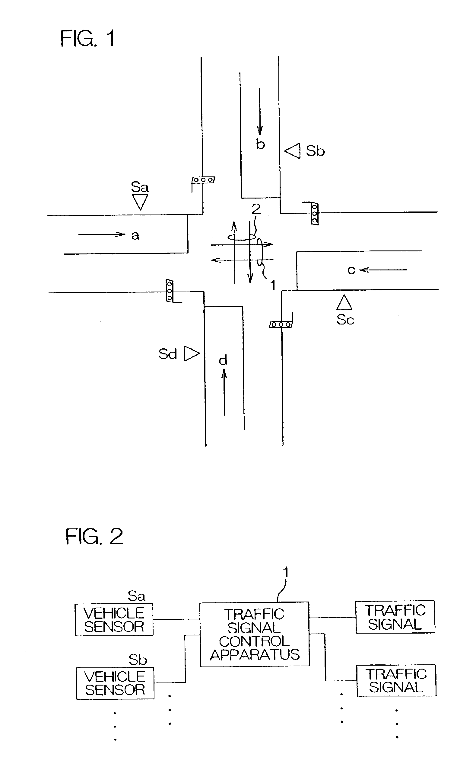
[0029]FIG. 1 is a plan view showing an intersection. Access roads are denoted by lower case letters a, b, c, and d, respectively. A vehicle sensor Sa is set up for the access road a, and likewise, vehicle sensors Sb, Sc, and Sd are set up for the access roads b, c, and d, respectively.

[0030]Changes of lights of the respective traffic signals for one cycle are set forth in Table 1 below.

[0031]

TABLE 11 CYCLEPHASEPHASE 1PHASE 2STEP12*3*45*6*ROAD aGREENYELLOWREDREDREDREDROAD bREDREDREDGREENYELLOWREDROAD cGREENYELLOWREDREDREDREDROAD dREDREDREDGREENYELLOWRED*Fixed Time

[0032]A period needed for the traffic signal to turn from a green light to a yellow light to a red light and to a green light again is defined as one cycle. Herein, let C be the time length of one cycle.

[0033]A time needed for the traffic signals o...


PUM


Abstract

In traffic signal control for setting a green light time to a value between the lower limit time and the upper limit time in real time depending on a traffic volume sensed by vehicle sensors Sa, Sb, and so forth, the upper limit time Gmax is set longer with an increase of a traffic volume on an access road corresponding to a phase in question (Steps T8 and T9). This arrangement is effective for use at an intersection where a traffic volume in one direction is far heavier than in any other direction, and thereby makes it possible to forestall the occurrence of traffic jam (FIG. 6).

Description

[0001]This application is based on application No. 2002-137494 filed in Japan on May 13. 2002, the content of which is incorporated hereinto by reference.BACKGROUND OF THE INVENTION[0002]1. Field of the Invention[0003]The present invention relates to a traffic signal control method for setting a time on a green light (hereinafter, referred to as the green light time) to a value between the lower limit time and the upper limit time in real time depending on a traffic volume sensed by a vehicle sensor or the like.[0004]2. Description of the Related Art[0005]Conventionally, the green light time of a traffic signal is controlled in the manner as follows.[0006]Vehicle sensors (a device capable of detecting a passing vehicle, such as an inductive loop sensor, an ultrasonic sensor and a camera; ditto for the description below) are set up for respective access roads to an intersection, and in a case where a traffic volume (the number of passing vehicles per unit time) is less than a predete...

Claims


Application Information

Patent Timeline
Patent Type & Authority Patents(United States)
IPC IPC(8): G08G1/07G08G1/08
CPCG08G1/08
Inventor NISHIMURA, SHIGEKI
Owner SUMITOMO ELECTRIC IND LTD
Why Eureka
Try Eureka