Portable computer having a latch apparatus

Inactive Publication Date: 2005-08-30
SAMSUNG ELECTRONICS CO LTD
View PDF15 Cites 25 Cited by
  • Summary
  • Abstract
  • Description
  • Claims
  • Application Information

AI Technical Summary

Benefits of technology

[0012]Accordingly, the present invention has been made keeping in mind the above-described shortcomings and a user's need, and

Problems solved by technology

However, in the structure of the latch apparatus according to the conventional portable computer 101, because the knob 135 must be moved from the locking position to the releasing position in order to release the latch member 133 from the latch ho

Method used


Image

  • Portable computer having a latch apparatus
  • Portable computer having a latch apparatus
  • Portable computer having a latch apparatus

Examples


Example

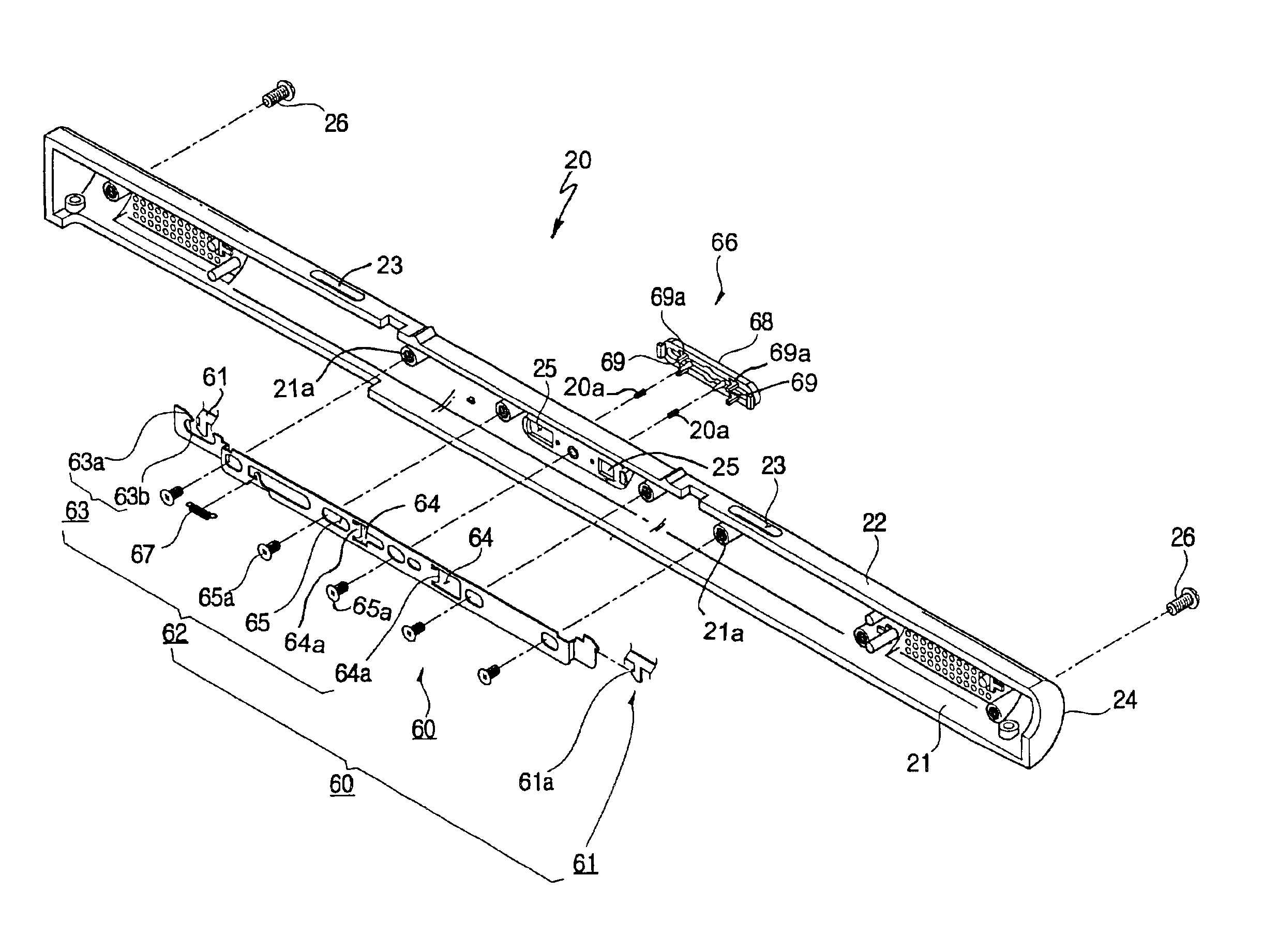
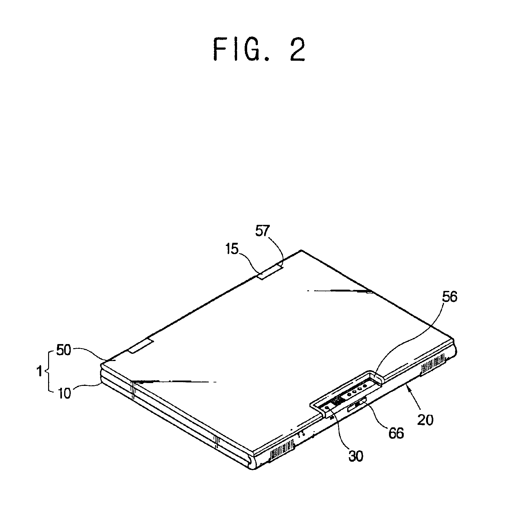
[0055]Referring to FIGS. 2 and 3, a portable computer 1, according to a first embodiment of the present invention, comprises a main body 10 which outputs a video signal, and an LCD assembly which displays the video signal received from the main body 10. The LCD assembly 50 has a free end 50a and is rotatably combined with the main body 10 at a hinged end 50b of the LCD assembly 50.

[0056]The main body 10 comprises a main board (not shown) mounted inside the main body 10. The main board is provided with a CPU (central processing unit), a RAM (random access memory), and other well known components of a portable computer. A keyboard 13 and a touch pad 11 employed as an input unit are provided on the main body 10. A rear part of the main body 10 is provided with a pair of hinge parts 15 which co-operate with hinge pins 16 to rotatably combine the main body 10 with the LCD assembly 50. A front portion of the main body 10 is provided with a front cover 20 which covers the front of the main...

Example

[0078]A second embodiment of the portable computer 1 of the present invention, incorporates an LCD opening unit 70 as shown in FIG. 13. The LCD opening unit 70 enables an operator to open / close the portable computer 1 with one hand. The opening unit 70 replaces the hinge pins 16, shown in FIG. 3.

[0079]Referring now to FIGS. 14 and 15, the LCD opening unit 70 comprises a first supporting part 71 removably combined to the main body 10, a second supporting part 75 removably combined to the LCD assembly 50, a rotation supporting part 80 having a hinge shaft 81 extended from the second supporting part 75 and a hinge shaft accommodating part 83 which rotationally receives the hinge shaft 81, and a torsion spring 85 surrounding the hinge shaft 81 and having first and second ends which engage the first and second supporting parts 71 and 75, respectively.

[0080]The first supporting part 71 is made of a durable material, such as for example, steel, and, as shown in FIG. 15, comprises a main pa...

Example

[0089]In a third embodiment of the present invention, the LCD opening unit 70 is alternatively constructed as shown in FIGS. 17, 18A and 18B. In a center area of one side of a main part 172 of a first supporting part 171, a stopper 91 which restricts a rotation angle of a shaft part 176a is provided. A contact part 176b is provided in one side of the shaft part 176a. The contact part 176b is positioned to contact the stopper 91 of the first supporting part 171 where the LCD assembly 50 is locked to or released from the main body 10 along forward or backward rotation directions. Thus, where the LCD assembly 50 is rotated toward the main body 10 as shown in FIG. 18B, the rotation of the shaft part 176a is restricted by the stopper 91 and the contact part 176b. Therefore, where the LCD assembly 50 is rotated toward the main body 10, the LCD assembly 50 maintains a predetermined angle Φ with a surface 10a of the main body 10. The surface 10 is indicated by dashed lines in FIG. 18B.

[0090...


PUM


Abstract

A portable computer having a latch apparatus and an opening unit which enable an operator to open the portable computer with one hand. A main body of the computer is rotatably combined with an LCD assembly. A latch apparatus locks the LCD assembly to and releases the LCD assembly from the main body. The latch apparatus includes a fixed hook part in the LCD assembly and a movable hook part in the main body. A knob part has a push button part exposed to the outside of the main body. A projection part of the knob extends from the push button part and moves the movable hook part to a releasing position by cooperating with a through hole of the movable hook part. The opening unit includes a torsion apparatus to assist in opening the portable computer.

Description

CROSS REFERENCE TO RELATED APPLICATIONS[0001]This application claims the benefit of Korean Application Nos. 2002-5681 and 2002-20267 filed Jan. 31, 2002 and Apr. 13, 2002, respectively, in the Korean Patent Office, the disclosures of which are incorporated herein by reference.BACKGROUND OF THE INVENTION[0002]1. Field of the Invention[0003]The present invention relates in general to a portable computer, and more particularly, to a portable computer having an improved latch apparatus by which an LCD assembly is locked to and released from a main body of the portable computer and to a portable computer having an opening unit which aids the latch apparatus in opening the portable computer.[0004]2. Description of the Related Art[0005]FIG. 1 is a perspective view of a conventional portable computer 101. As shown in FIG. 1, the conventional portable computer 101 comprises a main body 110; an LCD (liquid crystal display) assembly 120 rotatably combined to the main body 110; and a latch appa...

Claims


Application Information

Patent Timeline
IPC IPC(8): G06F1/16
CPCG06F1/1616G06F1/1656G06F1/1679G06F1/1681
Inventor PARK, BUM-SU
Owner SAMSUNG ELECTRONICS CO LTD
Why Eureka
Try Eureka