Waste toner collecting device, and image forming apparatus including the waste toner collecting device

a technology of waste toner and collecting device, which is applied in the direction of electrographic process apparatus, instruments, optics, etc., can solve the problems of jumboization complication of image forming apparatus, and difficulty in separating waste toner from paper dust, so as to prevent the occurrence of waste toner mal-distribution

Inactive Publication Date: 2005-08-30
RICOH KK
View PDF21 Cites 92 Cited by
  • Summary
  • Abstract
  • Description
  • Claims
  • Application Information

AI Technical Summary

Benefits of technology

[0023]Accordingly, an object of the present invention is to provide a waste toner collecting device which can be set in a free space of an image forming apparatus and need not be frequently replaced with an empty container by preventing occurrence of mal-distribution of a waste toner in a container.
[0024]Another object of the present invention is to provide an image forming apparatus which can perform image forming operations without frequently changing a waste toner container and in which the waste toner container can be easily replaced with a new container when the container is fully filled with waste toner.
[0030]It is preferable that the waste toner transport device includes a waste toner transporter provided in the container and a driving device configured to drive the toner transporter. It is preferable that the waste toner transporter is configured to transport the waste toner in a direction such that the waste toner is distanced from the one or more openings. The waste toner in the container is preferably transported by the waste toner transporter so as to move from a potion of the container having a shortest height to a portion having a longest height. It is preferable to arrange plural waste toner transporters in the container to effectively transport the waste toner. The waste toner transporter preferably includes at least one of a screw and a belt. The waste toner transporter is preferably provided under the openings. It is preferable that toner transporting capacity of the waste toner transporter is different in each portion thereof in such a manner that the shorter the height of a portion of the container corresponding to a portion of the waste toner transporter, the higher toner transporting capacity the portion of the waste toner transporter has.
[0031]The driving device preferably includes a driving motor and a drive force transmitting device configured to transmit the driving force of the motor to the waste toner transporter. The drive force transmitting device preferably has a spur gear (or a bevel gear) arranged on an end of the transporter and another gear configured to transmit the driving force of the motor to the spur gear. The drive transmitting device having such a configuration has better operation ability than drive force transmitting devices using a belt and a pulley.

Problems solved by technology

In order to reuse the waste toner, the image forming apparatus have to include passages through which the waste toner is collected and driving mechanism which feeds the waste toner, resulting in jumboization of the image forming apparatus.
In addition, the waste toner includes paper dust released from transfer paper sheets, but it is difficult to separate the waste toner from paper dust.
Further, in full color image forming apparatus using three or four color toners, the amount of the waste toners is large, and thereby a large container has to be set in the image forming apparatus, resulting in jumboization and complication of the image forming apparatus.
In this case, it is a problem to be solved how to efficiently collect the waste toner (i.e., how to fully fill the container with the waste toner) in order to reduce the container changing frequency.
The former technique has the following drawbacks:(1) noise is generated during the shaking operation;(2) a shaking mechanism has to be provided in the image forming apparatus;(3) since the containers shaken, a chock-full detector has to be provided in the container which is disposed of when the container is fully filled with a waste toner, resulting in increase of cost of the container; and(4) an operation such that a connector is connected to a chock-full detector is necessary when the container used is replaced.
The latter technique has the following drawbacks:(1) a leveling member is provided without taking into consideration of the shape of the container used, and thereby the waste toner piled is not fully leveled if the container has a complex shape;(2) the waste toner tends to firmly fix in the container when the waste toner is insufficiently leveled; and(3) a problem in that the waste toner overflows the container tends to occur when the waste toner is insufficiently leveled.
Therefore, a waste toner container tends to have a complex form because of being set in such a free space.

Method used


Image

  • Waste toner collecting device, and image forming apparatus including the waste toner collecting device
  • Waste toner collecting device, and image forming apparatus including the waste toner collecting device
  • Waste toner collecting device, and image forming apparatus including the waste toner collecting device

Examples


Embodiment Construction

[0052]The present invention will be explained referring to drawings.

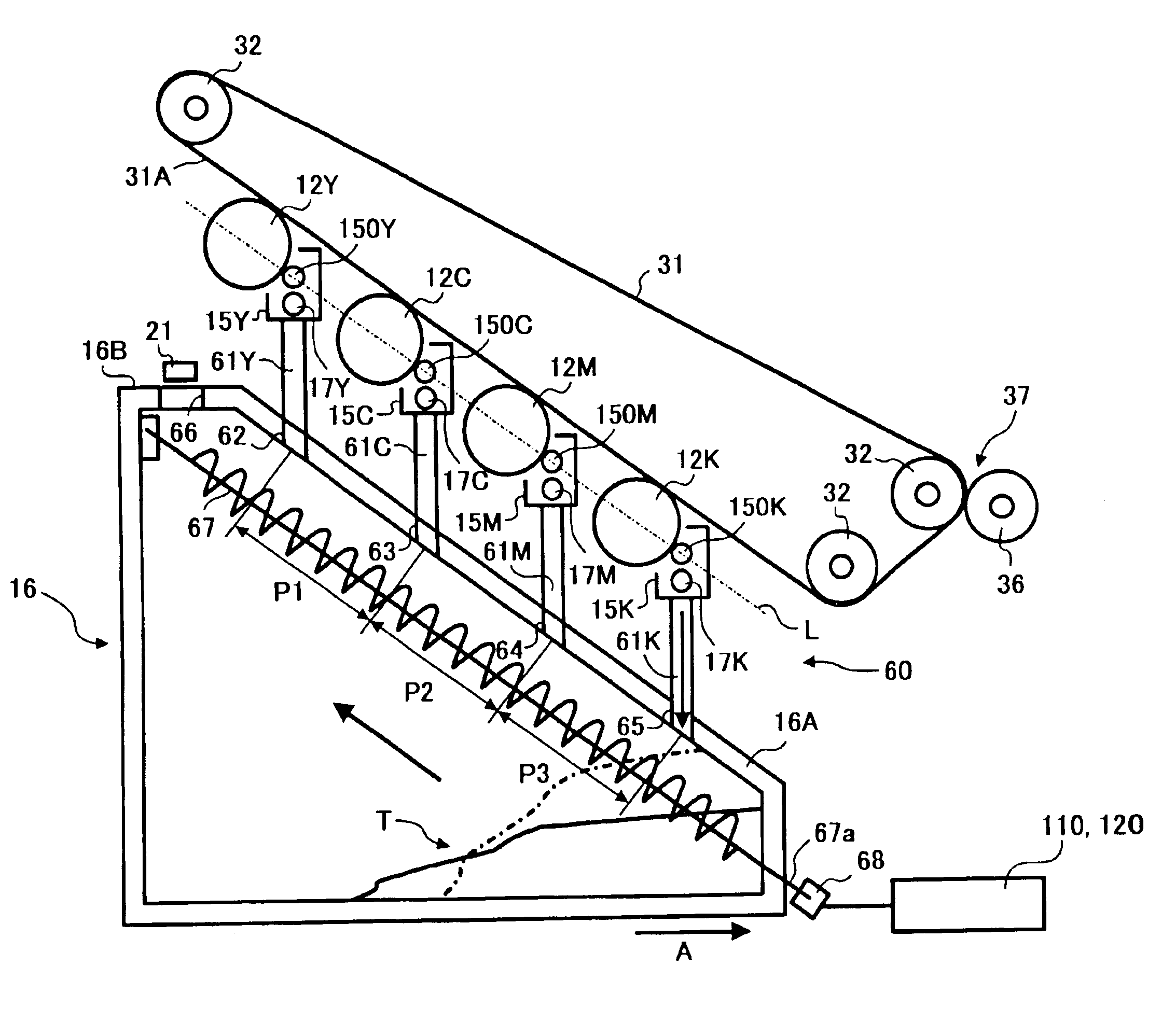
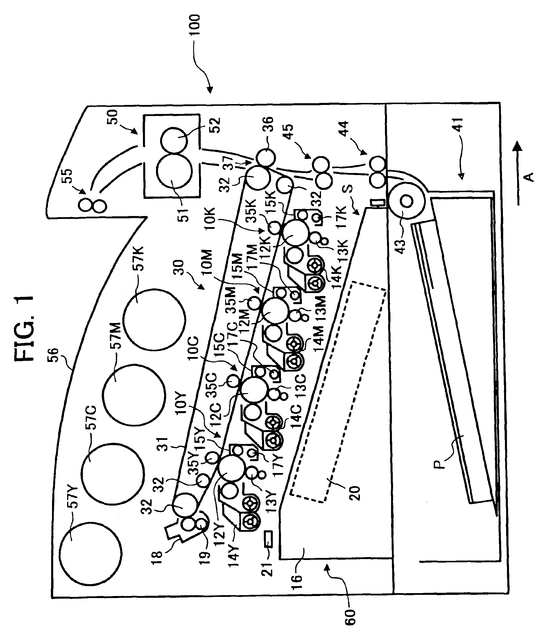
[0053]FIG. 1 is a schematic view illustrating a color printer which is an embodiment of the image forming apparatus of the present invention. Referring to FIG. 1, the color printer has a main body 100 and a paper supplying cassette 41 which is located below the main body 100 and which contains and feeds sheets of a receiving paper P.

[0054]The paper supplying cassette 41 can be attached to and detached from the image forming apparatus in the right and left direction in FIG. 1. The receiving paper P in the paper supplying cassette 41 is fed into the main body 100 by a paper supplying roller 43 and a pair of feeding rollers 44. A pair of registration rollers 45 are arranged at a position in a paper feeding passage between the pair of feeding rollers 44 and a second transfer portion 37, to timely feed the receiving paper P toward the second transfer portion 37.

[0055]The main body 100 includes image forming cartridges 10...


PUM


Abstract

A waste toner collecting device includes a container detachably set in an image forming apparatus and a waster toner transport device to transport waste toner in the container. The container has a shape as to fit into a free space of the image forming apparatus. The image forming apparatus also includes an image bearing member, and a cleaning device configured to collect a residual toner remaining on the image bearing member.

Description

BACKGROUND OF THE INVENTION[0001]1. Field of the Invention[0002]The present invention relates to a waste toner collecting device, and more particularly to a waste toner collecting device which collects and contains a waste toner produced by an image forming apparatus, which remains on an image bearing member and which is removed by a cleaner therefrom. In addition, the present invention also relates to an image forming apparatus including the waste toner collecting device.[0003]2. Discussion of the Background[0004]Recently, users of image forming apparatus such as copiers, printers, facsimiles and complex machines thereof perform operations such as change of consumable supplies of the image forming apparatus and maintenance operations that service men have conventionally performed.[0005]Recently, image forming apparatus have been miniaturized and the price thereof is reduced, and the constitutional parts of the image forming apparatus have also been miniaturized as much as possible....

Claims


Application Information

Patent Timeline
Patent Type & Authority Patents(United States)
IPC IPC(8): G03G15/01G03G21/12G03G21/10
CPCG03G21/12G03G21/105
Inventor ISHII, HIROSHIARAI, YUJI
Owner RICOH KK
Why Eureka
Try Eureka