

Integrated circuit with authomatic pin-strapping configuration
Active Publication Date: 2005-08-30
CIRRUS LOGIC INC
View PDF6 Cites 8 Cited by
- Summary
- Abstract
- Description
- Claims
- Application Information
AI Technical Summary
Benefits of technology
[0007]Any of the program select pins may have functions in addition to the configuration function and the present invention respects and, in fact, makes use of such other functions thereby reducing or even eliminating the need for special pins which are not used once the chip has been configured.
Problems solved by technology
It will be appreciated that it may be impractical to use a separate chip design for similar applications.
However, in the past, it has also been impractical to fine tune chips with external components.
Method used
View moreImage
Smart ImageViewing Examples

Examples
example
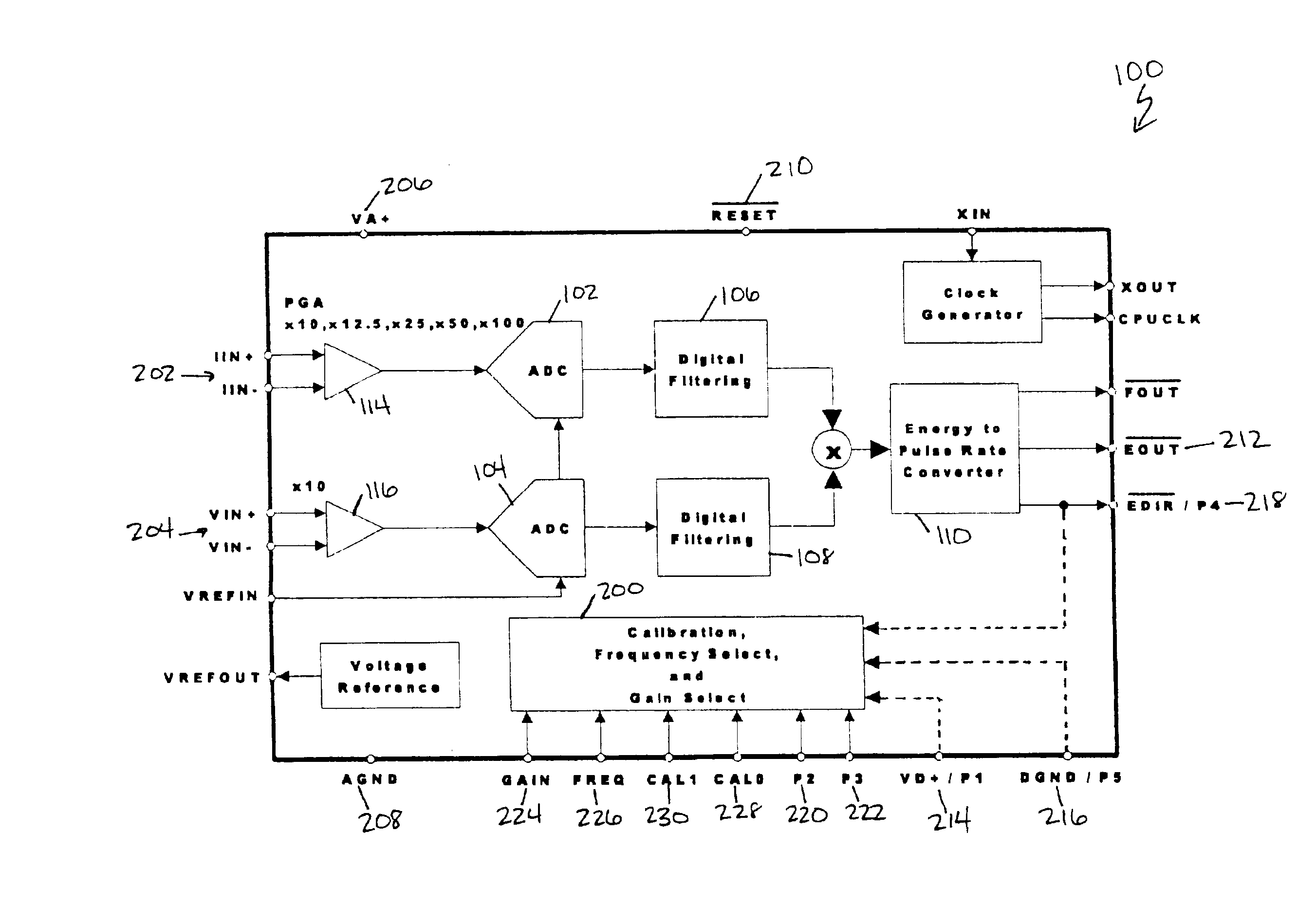
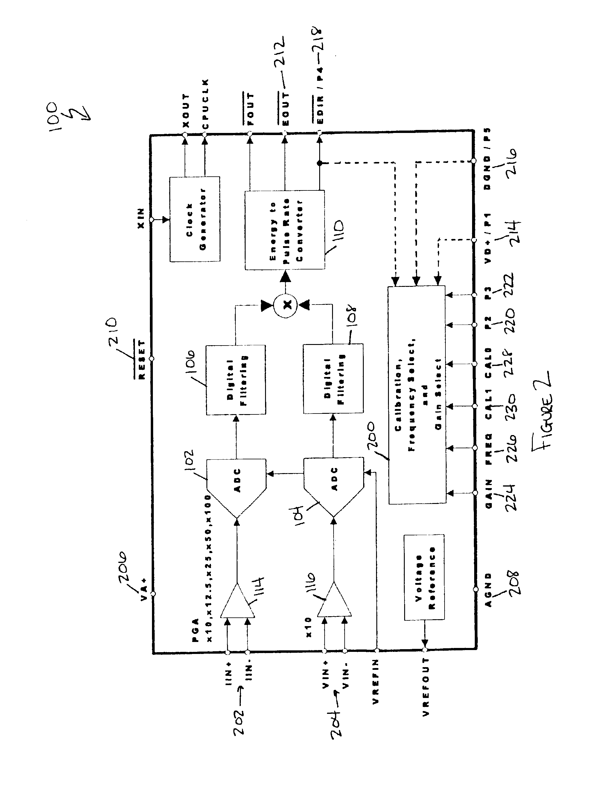
[0027]FIG. 3 illustrates an integrated circuit (the exemplary CS5462) 100 of the present invention mounted on a system board 300. The board 300 is connected to a single-phase, two-wire service mains 302 and various board components are connected to the chip 100 to measure the power used. The power is tracked by and read from a mechanical counter 304. The configuration pins 224-228 are tied to the program select pins P1-P5214-218 through jumpers or the like 306 on the system board 300.
Login to View More PUM
 Abstract
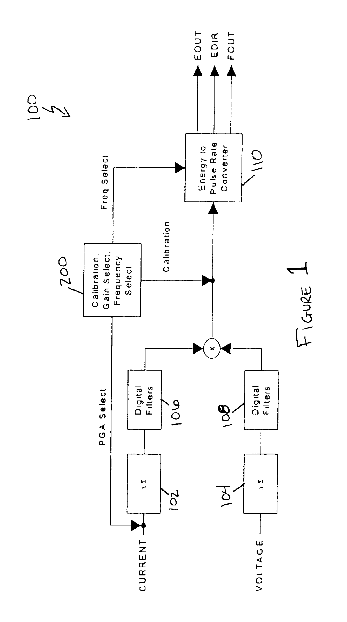
An integrated circuit, in which one or more internal parameters may be automatically configured for a particular application, includes a plurality of program select pins, each being in a predetermined fixed state, and at least one configuration pin associated with a parameter to be adjusted. Jumpers on the system board to which the integrated circuit is mounted connect the mounting pad of each configuration pin with the mounting pad of a selected program select pin. Consequently, when the integrated circuit is mounted on the system board, each configuration pin receives a selected value which internal configuration circuitry detects and causes the corresponding parameter to be adjusted accordingly. Any of the program select pins may have functions in addition to the configuration function. When the system board is powered on or undergoes a reset, a processor internal to the chip scans each the configuration pin to determine its value. The processor then sets internal registers accordingly, completing the configuration process, and the chip may begin normal operation.
Description
TECHNICAL FIELD[0001]The present invention relates generally to the field of integrated circuits in general and configuration of internal parameters in particular.BACKGROUND ART[0002]An integrated circuit or “chip” is generally installed on a system board which is ultimately installed in an end product. Commonly, an integrated circuit may be purchased for use in several (or many) different end products, often by different manufacturers. Consequently, a single chip design may have to be “fine tuned” or configured for optimal performance in a particular product. Moreover, due to tolerances and other inaccuracies in other components, it may even be important to be able to configure each chip when it is installed on the system board.[0003]It will be appreciated that it may be impractical to use a separate chip design for similar applications. However, in the past, it has also been impractical to fine tune chips with external components. One known technique requires that specified pins o...
Claims
Login to View More Application Information
Patent Timeline
 IPC IPC(8): H03K19/173
CPCH03K19/1732
InventorBREEJEN, FRANK DENBIVEN, DAVID MICHAELTORKE, WILLIAM JAMESGARDEI, WILLIAM F.
OwnerCIRRUS LOGIC INC