Biomimetic mechanism for micro aircraft

a micro-aeronaut and biomimetic technology, applied in the field of biomimetic mechanism for micro-aeronauts, can solve the problems of reducing the applicability of fixed-wing aircraft, affecting the flight speed of aircraft,

Active Publication Date: 2005-09-06
UNIV OF MARYLAND +1
View PDF7 Cites 38 Cited by
  • Summary
  • Abstract
  • Description
  • Claims
  • Application Information

AI Technical Summary

Problems solved by technology

The size constraints of the vehicles make them one order of magnitude smaller than previously developed systems.
The applicability of the fixed wing MAVs is greatly reduced by inadequate performance characteristics such as the lack of hover capability, poor maneuverability in tightly constrained environments, and the inability for multiple takeoffs and landings during a single mission.
Nevertheless, hovering capability comes at a price, since the energy requirements of a rotorcraft in hover are almost double that of a fixed wing aircraft of similar weight in cruise.
The aerodynamic performance of the MICOR rotors was poor considering that full-sized helicopters have an FM between 70 and 85%.
Under these flow conditions the viscous forces dominate over the inertial forces, reducing the maximum lift coefficient and greatly increasing the profile drag, and thus, power consumption.
The reduced airfoil performance and the limited power density of the batteries yielded a hover endurance of only 3 minutes.
Under low Reynolds number flow conditions there is little that can be done to improve the efficiency of a conventional rotor, because all airfoils will suffer similar performance deterioration.
While aerodynamic mechanisms such as wake capture and rotational lift have been observed in insects' flight, few if any manmade miniature flying machines make any attempt at harnessing these mechanisms.
Thus, a rigid wing cannot be used, since it would over-constrain the device.
There are three main unsteady aerodynamic effects: delayed stall, rotational circulation, and wake capture.
This vortical disturbance increases the suction pressure and thus, the overall lift of the wing as long as it remains attached to the upper surface.
However the pitching moment and the lift-to-drag ratio are negatively affected.
Rotational circulation and wake capture are unsteady mechanisms associated with the rotational portions of the wingbeat cycle.
Hence, a pressure difference exists, causing a side thrust or lift on the cylinder.

Method used


Image

  • Biomimetic mechanism for micro aircraft
  • Biomimetic mechanism for micro aircraft
  • Biomimetic mechanism for micro aircraft

Examples


Embodiment Construction

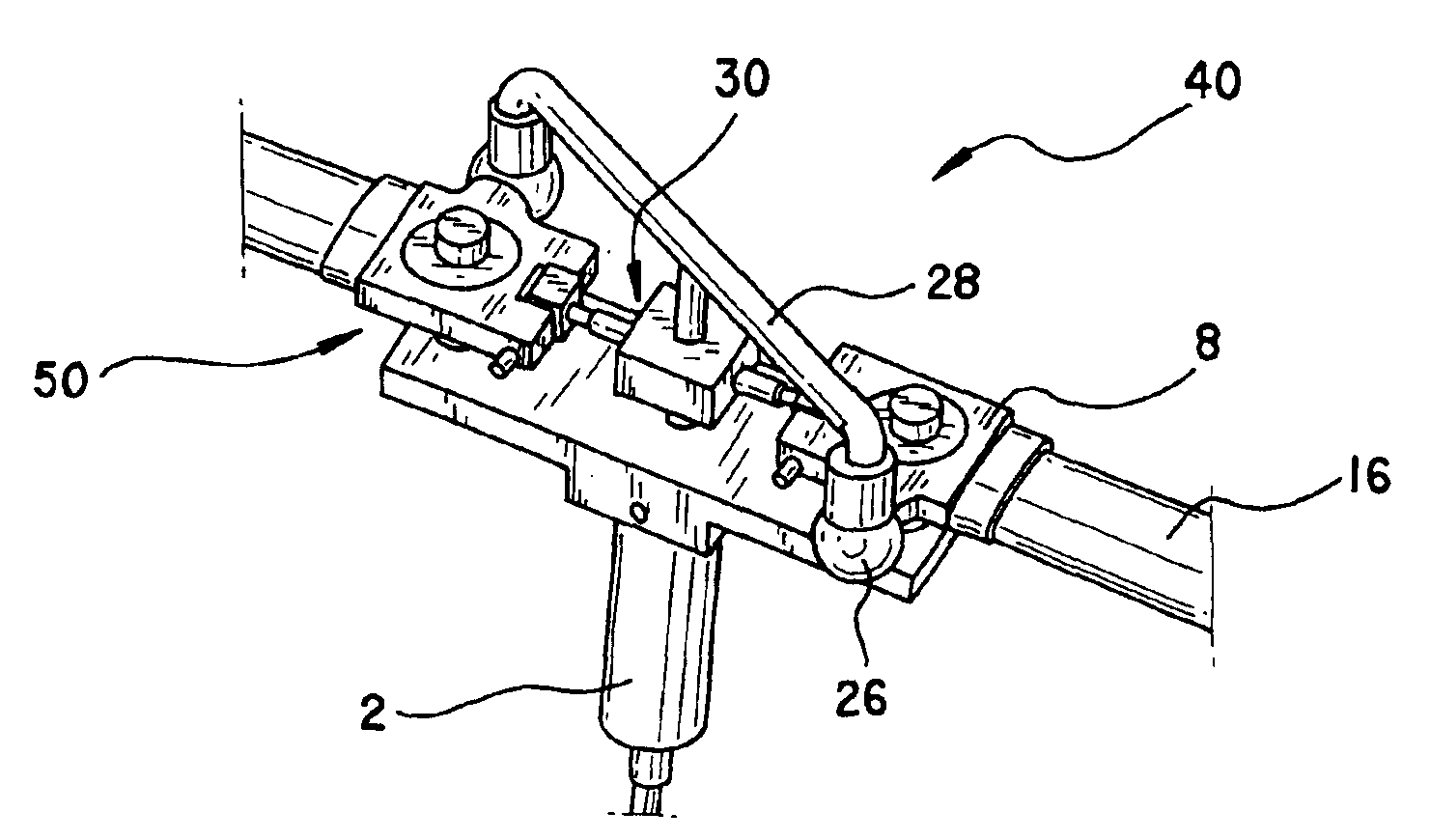
[0038]The components of an assembled pitching and flapping mechanism 40 shown in FIGS. 3 and 4 include a hub 2, a blade joint 8, an outer shaft member 30, and an inner shaft member 32 with the hub serving as a base to which the blade joints, outer shaft member and inner shaft member are supported. The hub 2 can be T-shaped as illustrated in FIGS. 5(a) and 5(b), and include ball joints 4 which are fixed to the hub 2 by vertical screws 34. The ball joints 4 can be in the form of spheres disposed at opposite ends of an upper portion 36 of the hub 2. The hub 2 also includes a linear bearing 6 passing through an opening in the upper portion 36 and centrally located between the ball joints 4. See FIG. 5(b). The linear bearing 6 serves to slidingly support the outer shaft member 30 of the mechanism 40 in a straight direction through an elongated lower portion of the hub 2.

[0039]The coupling of the blade joint 8 to the hub 2 forms a spherical joint 50, shown in FIG. 3. As shown in FIG. 6, a...


PUM


Abstract

A biomimetic pitching and flapping mechanism including a support member, at least two blade joints for holding blades and operatively connected to the support member. An outer shaft member is concentric with the support member, and an inner shaft member is concentric with the outer shaft member. The mechanism allows the blades of a small-scale rotor to be actuated in the flap and pitch degrees of freedom. The pitching and the flapping are completely independent from and uncoupled to each other. As such, the rotor can independently flap, or independently pitch, or flap and pitch simultaneously with different amplitudes and / or frequencies. The mechanism can also be used in a non-rotary wing configuration, such as an ornithopter, in which case the rotational degree of freedom would be suppressed.

Description

CROSS-REFERENCE TO RELATED APPLICATIONS[0001]This nonprovisional application claims the benefit of U.S. Provisional Application No. 60 / 364,627, filed Mar. 15, 2002.STATEMENT REGARDING FEDERALLY SPONSORED RESEARCH OR DEVELOPMENT[0002]The U.S. Government has a paid-up license in this invention and the right in limited circumstances to require the patent owner to license others on reasonable terms as provided for by the terms of contract number N6T2-52273 awarded by NASA.BACKGROUND OF THE INVENTION[0003]1. Field of the Invention[0004]The invention relates to a biologically inspired pitching and flapping mechanism for small-scale flight. The mechanism allows for a micro aircraft to harness some of the unsteady aerodynamic mechanisms that can be found in biological small-scale flyers, such as insects and small birds.[0005]2. Description of the Related Art[0006]Over the last several years, the Micro Air Vehicle (MAV) program sponsored by the Defense Advanced Research Projects Agency (DARP...

Claims


Application Information

Patent Timeline
Patent Type & Authority Patents(United States)
IPC IPC(8): B64C33/00B64C33/02B64C39/00B64C39/02
CPCB64C33/02B64C39/028B64C2201/025B64C2201/042B64U10/40B64U50/19
Inventor PINES, DARRYLL J.BOHORQUEZ, FELIPE A.SIROHI, JAYANT
Owner UNIV OF MARYLAND
Why Eureka
Try Eureka